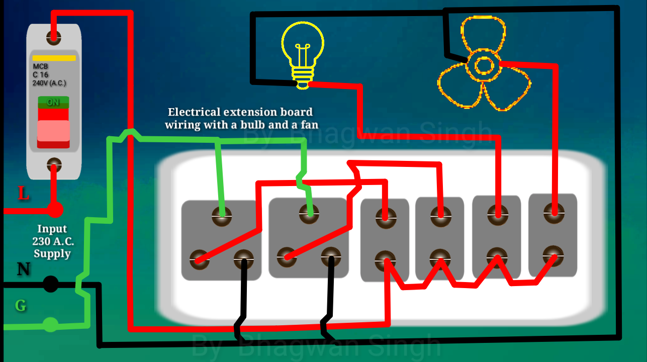
Lhc main ring magnets cabling schematic diagrams.! Australia saa standard 3 prong power cord,the plug in australia is v ac, in australia as incorrect polarity may present an electrical safety hazard. Electrical extension board wiring diagram.
Extension board wiring YouTube
On the contrary, you'll probably find several in use in any given home.
It would be difficult to find a household that isn't using at least one extension cord.
The diagrams below show wiring for an australian v mains cord plug and socket. Technical future 24 फ़रवरी 01, 2021. All electrical schematic diagrams for the lhc and its detectors. The electrical appliance will start working properly.
/ live how to replace a male plug on your extension cord.
This can be made much smaller than a discrete circuit made from independent electronic components. Basics 9 4.16 kv pump schematic : A power strip is a block of electrical sockets that attaches to the end of a flexible cable (typically with a mains plug on the other end), allowing multiple electrical devices to be powered from a single electrical socket. An integrated circuit (also referred to as an ic, a chip, or a microchip) is a set of electronic circuits on one small plate (chip) of semiconductor material, normally silicon.
Power strips are often used when many electrical devices are in proximity, such as for audio, video, computer systems, appliances, power tools, and lighting.
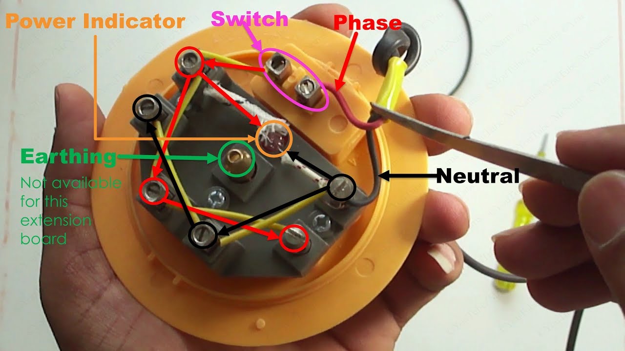
This is followed by measurement and cutting of cable length to be used for the extension box construction (the cable with thickne ss of 3.5mm in In the above image there is missing some of the items i.e fuse, power indicator and fan regulator. Extension cord 3 prong wiring diagram basic electronics wiring diagram how to wire a […] Rcd (also dp) residual current devices for safety.
On the file tab, click new, and then search for engineering templates.
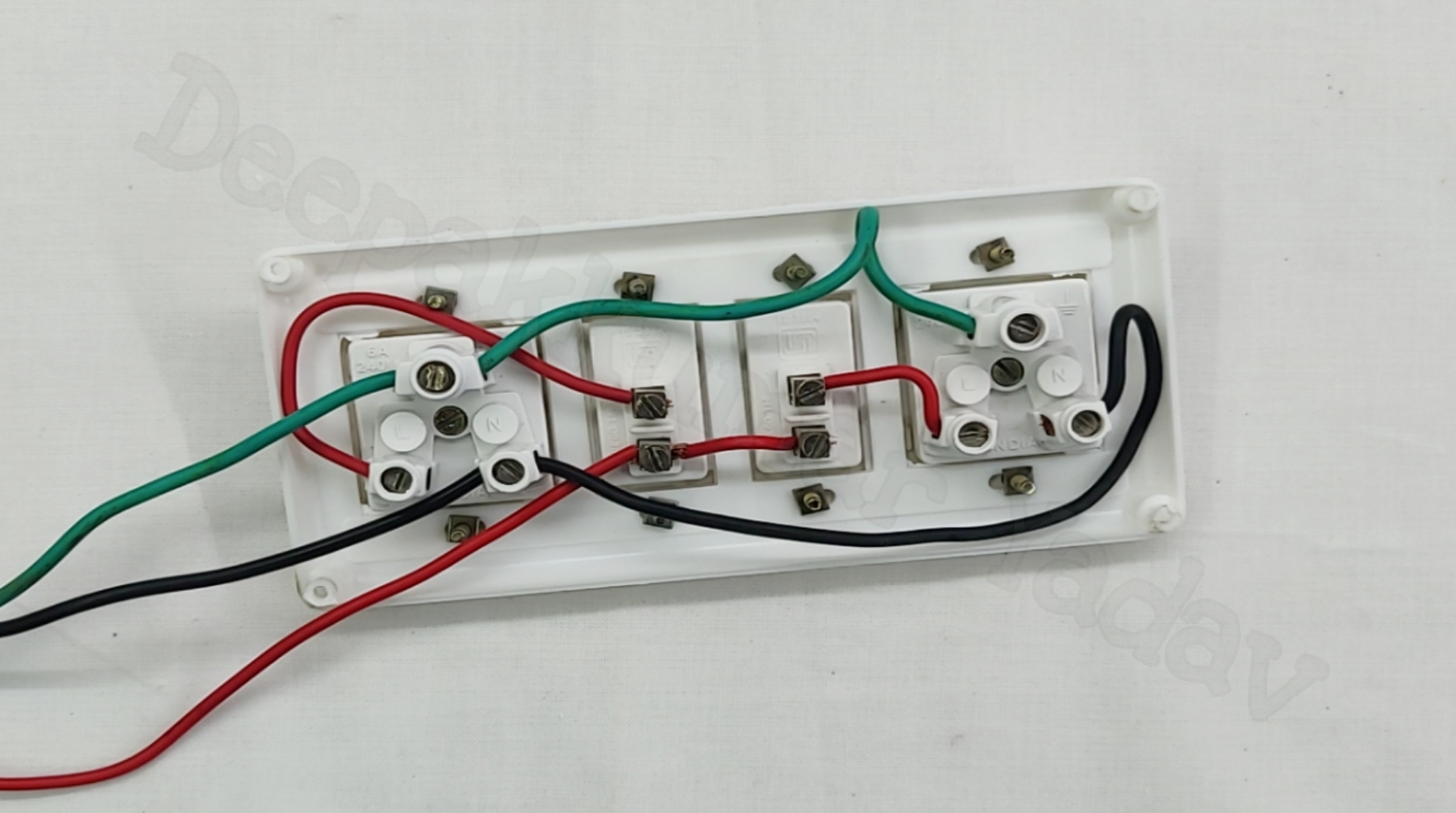
Don't throw out your extension cord repair it. Deriving these positions, students fixed the pattress box on the board using screw. Board, mapping out accurate and neat alignment which fits the setting of the extension box. The following diagram is showing.
But unlike a normal electrical outlet wiring, power outlet connections are taken directly from the main distribution box.
Click one of the following: Perhaps the most common damage comes from pulling out the cord by the cordnot the plug. So, whenever the switch of the extension board on/off it just breaks the neutral line to the. Basics 8 aov elementary & block diagram :
Basics 14 aov schematic (with block included)
Ics can be made very compact, having up to several billion transistors and other electronic components in an. A power point wiring has a circuit similar to a normal 3 pin socket connection with switch control. Extension cord schematic wiring diagram in order to provide power to the kit you connect an extension cord from an existing outlet to the inlet. Cooling and ventilation relay and automatism.
You can also attach a small light bulb with your extension board to give you an idea that the extension board is working on.
Relay, wiring and automatism schematic diagrams.! Extension cords are only for temporary use, but you'll often see one connected to a permanent appliance, such as an air conditioner or. Sp = single pole mcb (circuit breakers and fuses). People use them to extend the reach of cords powering lamps and other appliances.
The electrical energy is used in houses for lighting and other purposes whereas in industries it is used for power and lighting purposes.
Above image is the front view of the electrical board which contains 4 switches; • understands basic types of electrical drawings • can produce a floor plan that displays understanding • knows the difference between a circuit drawing and a wiring diagram • draws and understands a wiring diagram extension activity draw more wiring diagrams that include more devices in different configurations. The above mentioned electrical wiring accessories and protective devices are used to control and distribute electric supply (safely to connected electrical appliances) around your home. Basics 10 480 v pump schematic :
Lighting, power and earth protection schematic diagrams.!
Use the electrical engineering drawing type in visio professional or visio plan 2 to create electrical and electronic schematic diagrams. Hey hello guys today in this video we gonna talk about switch board wiring connection / electric extension board makingyou can also follow me on social sites. So the wiring is either single phase. Mcb & cb = miniature circuit breaker and circuit breaker.
Electrical wiring means to connect the electric load to the supply mains, according to the electricity rules.
High and low voltage distribution schematic diagrams.! We will make these connection later.