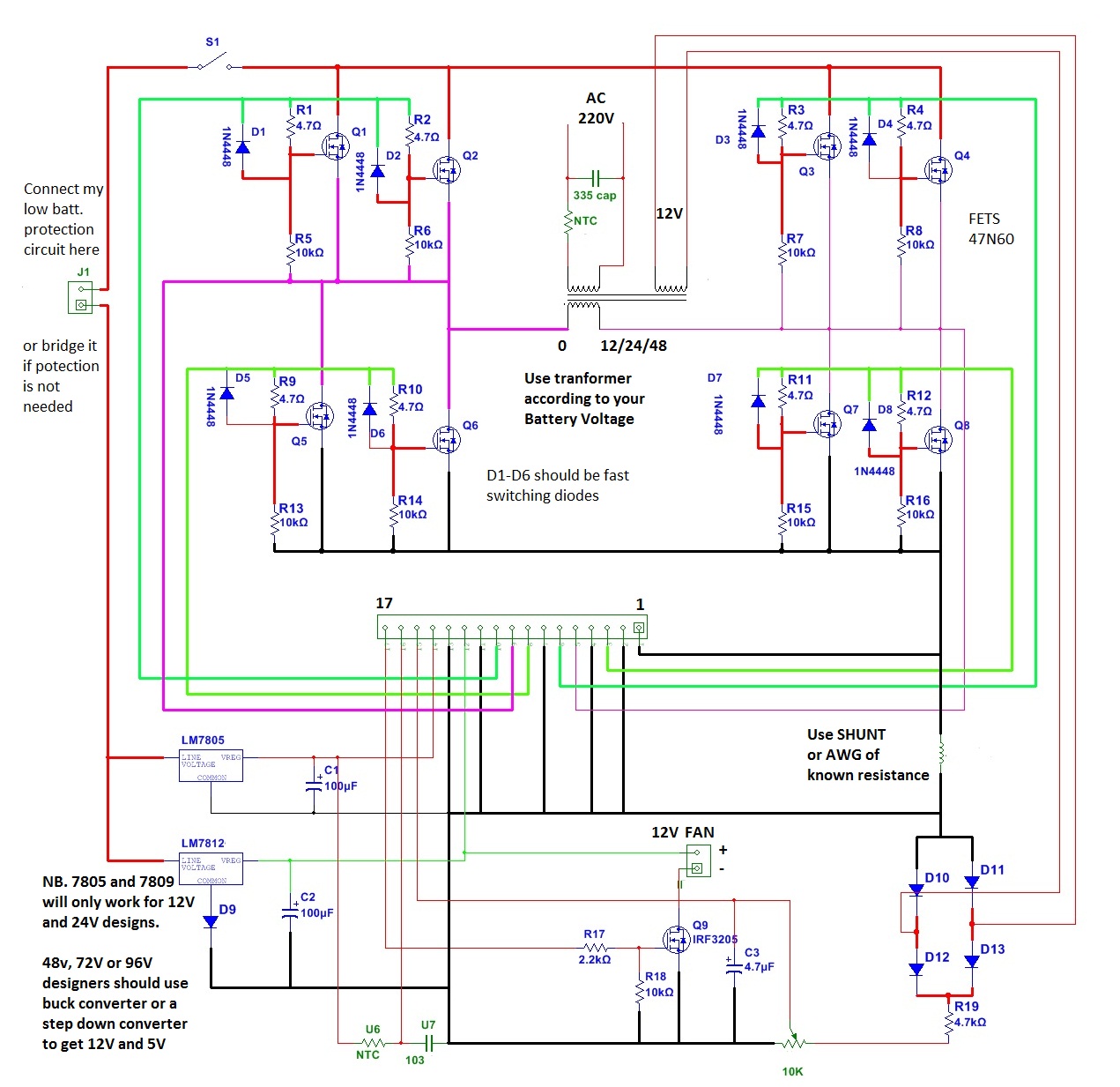
So hopefully, no more blown fet’s. 4 pin set of pure sine wave output frequency: Egs002 sine wave inverter circuit.
Egs002 Inverter Circuit Diagram Pdf / Thebackshed Com
With this modification the inverter can handle current peaks.
It uses asic eg8010 as control chip and ir2110s as driver chip.
And now for the modification on egs002. Egs002 is a driver board specific for single phase sinusoid inverter. We stock many different types of power inverters for almost any type of application. Homemade 2000w power inverter with circuit diagrams.
Few days ago, gohz made a 24v 2000w power inverter in home, sharing some design schematics and circuit diagrams.
It uses asic eg8010 as control chip and ir2110s as driver chip. 12v dc to 220v ac converter circuit using astable multivibrator. Remove the 8 components with red a cross. Johnny78 full member level 2.
Egmicro, alldatasheet, datasheet, datasheet search site for electronic components and semiconductors, integrated circuits, diodes, triacs and other semiconductors.
The inverter prototype was designed by using pulse width modulation (pwm) signal generated by egs002 module, combined with dc voltage source, voltage regulator, mosfet bridge and. Egs002 is a driver board specific for single phase sinusoid inverter. The inverter application requires two outputs that are 180 degrees out of phase. The inverter prototype was designed by using pulse width modulation (pwm) signal generated by egs002 module, combined with dc voltage source,.
Id name designator footprint quantity mounted;
Pure sine wave inverter circuit with no center tap design has become sim. The driver board integrates functions of voltage, current and temperature protection, led warning indication and fan control.jumper configures 50/60hz ac output, soft. Egs002 sinusoid inverter driver board user manual 1. Find this pin and more on matondo by muanza matondo.
Finally, set the tfb variable resistor so that it reads 0v on the ifb pin.
(same as the temp method, but the right way to do it). Joined jun 28, 2017 messages 121 helped 0 reputation 0 reaction score 0 trophy points 16 activity points 854 hi. Mar 18, 2022 #1 j. Inverter circuit 500w 12v to 220v eleccircuit com.
Lift pin 7 on the cpu.
Set the ifb variable resistor so that it reads 0v on the ifb pin. Egs002 eg8010 + ir2113 pure sine wave inverter spwm module. A relatively simple 1000 watt pure sine wave inverter circuit is explained here using a signal amplifier and a power transformer. Egs002 sine wave inverter circuit this is a simple sine wave inverter circuit without programming.
With this mod, the spwm enable pin, can enable and disable the sinewave out.
If you have a need for a 12v, 24v or 48 volt model, you have come to the right place as we have been selling them since 2003! Cp2102 usb to ttl copy. Sinusoid inverter driver board, egs002 datasheet, egs002 circuit, egs002 data sheet : Start date mar 18, 2022;
Next, set the ifb variable resistor so that it reads 3v on the ifb pin.
Turn off the power, then insert module egs002. Using an inverter circuit taken from the eg8010 datasheet with a few changes.


