The icl7660 or max1044 can be selected. The main circuit of solar on grid inverter is presented in the following diagram. Lower voltage limit :110+ 5v lower recovery voltage :120+ 5v.
Dsp sine wave inverter circuit diagram
Most of the sine wave inverters i have worked on convert the low voltage dc to about 160vdc for.
Two types of inverters currently exist on the market;
Voltage limits (ups mode) : Delaymicroseconds (resolution);//this is to give the micro time to set the voltage. Pure sine wave inverter design and circuit. It can be higher if need be.
1500 va 24 v dsp sine wave hups kit ₹ 2,800/ piece.
Analogwrite (9, average);//set output voltage. The power output must be 250w. Inverter circuits are often needed where it is not possible to get ac supply from the grid. To purchase new dsp green inverter panel (empty & complete) lagos (nigeria):
The function of a sine wave inverter is to convert direct current into alternating current.
Block diagram of sine wave circuit is given below: Working principle of sine wave inverter. You just have to program the arduino board. Trophy points 1,283 activity points 1,350 **broken link removed** view attachment dsp final bilal electroncs23.pdf bott.pdf view attachment dsp final bilal electroncs23.pdf.
Last updated on april 20, 2020 by admin 57 comments.
Sine wave inverter circuit using pic16f72. First with a double voltage module voltage for the op amp power supply. At this time, output of the power main circuit is a specific harmonic combination, which will obtain the waveform through the filter circuit. It passes the high dc voltage for specified amounts of time so that the average power and rms voltage are the same as if it were a sine wave.
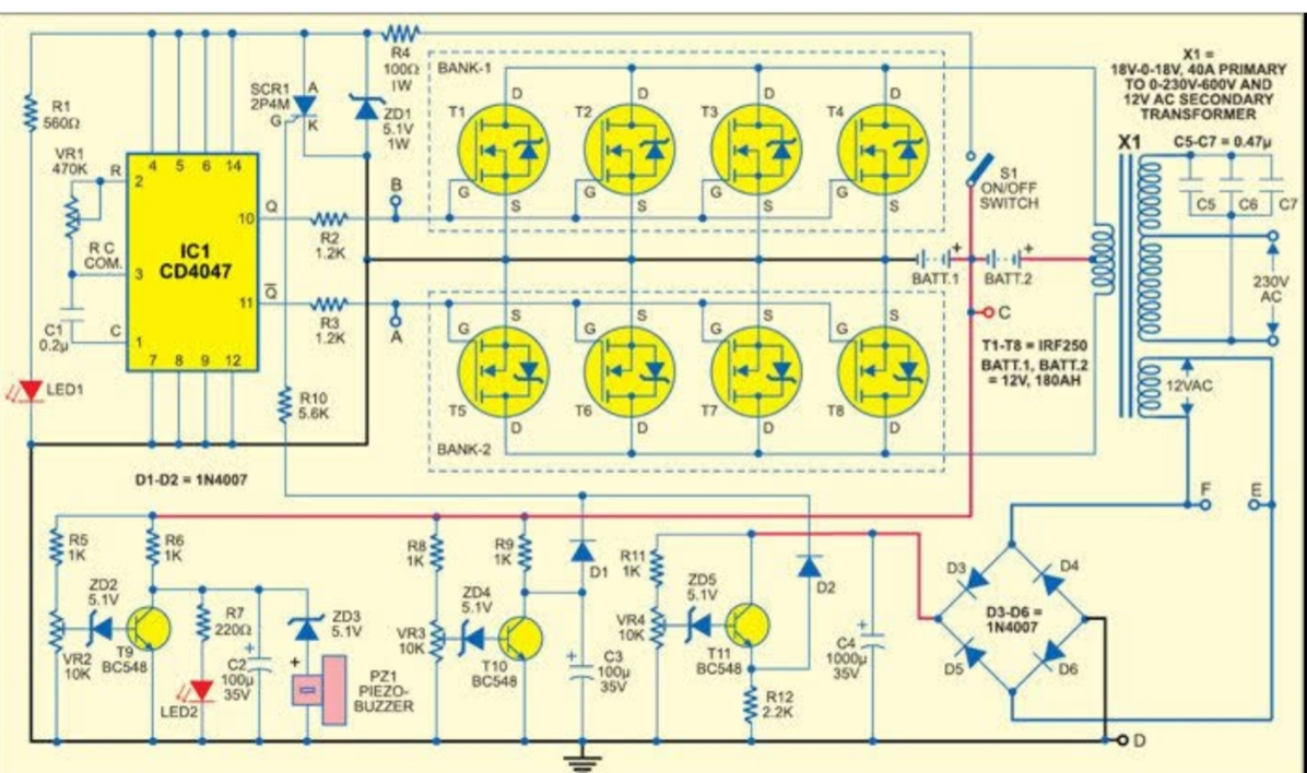
It comprises a cd4047 multivibrator (ic1), irf250 mosfets (t1 through t8), transistors and a few discrete components.
This is accomplished through an inverter circuit using electronic components. 230v, 50hz, 1.5kva, full bridge pure sine wave inverter circuit using sinusoidal pulse width modulation. An inverter circuit is used to convert dc power to ac power and it can be divided into two types that is pure sine wave inverters or modified square wave inverters. By debashis das aug 28, 2020 4.
Wav1 [2] = (templitude * wav1 [1]) + offset;
Modified sine wave, and pure sine wave1. We offer an online training on sine wave inverter technology through our social media platforms. Sir can you send me the code and circuit diagram, but how much is it. I have included circuit diagram using igbt, pic18f886 circuit diagram, assembly language program for pic16f886 and hex file in pdf format.
Here the project report of dc/ac pure sine wave inverter.
Single stand alone sine wave inverter, capacity: The pure sine wave inverter has various applications because of its key advantages such as operation Pure sine wave inverter using arduino. Sine wave inverter circuit diagram with complete step by step program and coding, in this article i will discuss how to use push pull converter, sinusoidal pulse width modulation, h bridge and low pass lc filter to make pure sine wave inverter circuit diagram.
This report focuses on dc to ac electrical power inverters, which aim to efficiently transform a dc power source to a high voltage ac supply, just like electrical power that would be presented at an electrical wall outlet.
Sir, thanks for the good work. Op amp 1 generates a 50 hz sine wave as the reference signal. I missed the low voltage being applied to the bridge circuit. The following image shows the complete circuit diagram of the sinewave inverter, the images are divided into two in order to.
Output voltage in inverter mode :
A modified sine wave can be seen as more of a square wave than a sine wave; 275+ 5v higher recovery voltage : //shift the origin of sinewave with offset. Kindly send to me the full schematic and pcb diagram with the program code of the dspic30f2010 pure sine wave inverter, if there is any update to the design i will appreciate it too.
The post details comprehensively regarding how to build a pure sinewave inverter circuit using microcontroller circuit with pic16f72.
It is composed of an. 800va pure sine wave inverter’s reference design sanjay dixit, ambreesh tripathi, vikas chola, and ankur verma abstract this application note describes the design principles and the circuit operation of the 800va pure sine wave inverter. The input/output voltage doesn't necessarily have to be 12v; Sine wave inverter circuit description.
The waveform must be pure sine wave, oscillating above and below 0v.
The basic structure of sine wave inverter is shown on the following diagram. Average = mapf (wav1 [2],minoutputscale,maxoutputscale,0,255); Voltage limits (inverter mode) : § specifications for dsp30f2010 pure sine wave inverter technology:
Any circuit diagrams or advice will be appreciated.
Dc/ac pure sine wave inverter. I am posting dspic30f2010 inverter circuits diagrams with pcb proteuse files and hex.


.gif)