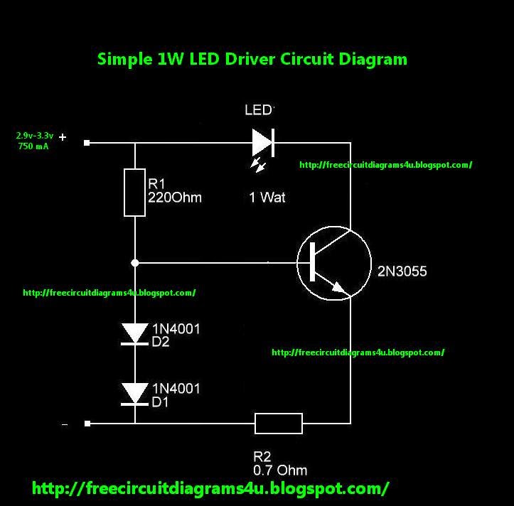
Again, don’t worry, here we will see how to wire a parallel led circuit and that should help tie the ideas. An led driver is an electrical device that regulates the power of an led or a string (or strings) of leds. 1w, 4w, 6w, 10w, 12w led driver circuit smps.
Analog Dimming LED Driver Circuit YouSpice
Its cheapest project in english.
Where a series circuit receives the same current to each led, a parallel circuit receives the same voltage to each led and the total current to each led is the total current output of the driver divided by the number of parallel leds.
12v is less than 24.5v so ok there. However, the dimming effect can be perhaps implemented by connecting the series led section of the led bulb with the ic 555 circuit, as indicated in the following diagram: 50 watt led driver circuit diagram. Touch dimmable led light bar circuit.
1a + 100ma = 1.1a is the minimum.
Low intensity = r2 = 0.7/1 = 0.7 ohms, wattage = 0.7 x 1 = 0.7 watts or 1 watt. The 555 timer is used to generate a pwm signal with. The idea was requested by one of the avid readers of this blog. Four white leds are connected with the led pin5 and to the q1 mosfet drain pin, gate terminal of si2302 is connected with ctrl pin of lt3491 and pwm out pin of.
1a (1000ma) looked up in the current limit resistor table results in a 549 ohm resistor 12v (led v max) + 0.5v = 12.5v is the minimum output voltage that the power supply can put out and be usable.
Led driver compact dimming 4.1.5 thd vs load 4.1.1 efficiency vs load 4.1.2 power factor vs load 4.1.4 input current vs load 4.1.3 input power vs load 4.1.6 phase cut dimming curve (depends dimmer) output current vs dimming 4. Electrical values 4.1 diagrams lc 8w 180ma fixc pc sr snc2 ˜ ˚ ˛˝ ˙ˆ ˆ ˇˆ ˘ˆ ˛ˆˆ ˛˛ˆ ˙ ˇ ˘ ˛ˆ. Here's the required working concept. R2, r3, r4 could be determined as:
We know that an led bulb circuit is nothing but a small ac to dc smps circuit, which employs a small ferrite transformer for stepping down the mains voltage to a lower led dc.
R1 may be calculated by using the following formula: A triac dimmable led driver circuit comprises an input ac voltage source connected to a rectifier bridge and an led load, the led load is connected to an inductor or a transformer, a power mos transistor, a low voltage mos transistor and a current sensing resistor, the inductor or transformer includes at least two windings, the first winding is connected to the power mos. Gx_2680 1w led driver circuit diagram watt led circuit diagram 1 watt led wiring diagram. All ir led driver circuit wholesalers & ir led driver circuit manufacturers come from members.
An led driver responds to the changing needs of the led, or led circuit, by providing a constant quantity of power to the led as its electrical properties change with temperature.
This led light bar with dimmable feature will allow the user to adjust the brightness of the lamp in 4 steps, with100%, 50%, 10% and 0% illumination control at each subsequent steps. 10v (led vmin) + 6v = 16v is the maximum output voltage that the power supply can put out and be usable. 5.1 what is led driver circuit. Schematic of the led brightness control circuit.
We doesn't provide ir led driver circuit products or service, please contact them directly and verify their companies info carefully.
A 12v dc source is used to power the entire circuit including the 555 timer ic and the leds. The offered smps led driver circuit is exceedingly adaptable and in particular fitted to driving. This design operates with an input voltage ranging from 185 vac to 265 vac and provides an output of 48 v at 120 ma that is capable of driving a nominal led string voltage. The following image depicts the block diagram of the pwm based led dimmer using 555 timer ic.
Dimmers, and 120v/277v dimming systems compatibility:
And the only way to change the. The occasion for this project was retrofitting an illuminated wall picture with led backlighting. As soon as i applied led power, the brightness blinded me — much brighter than the original t20 fluorescent tube, so i knew immediately that a dimmer control was required. 50 watt led driver circuit.


