Digital multimeters convert analog signals to digital information. While specifications vary, most dmms can be described with block diagrams. The above circuit looks like a multi range dc voltmeter.
Digital multimeter circuit using ICL7107
Each industrial meter is tested to the extreme:
The following figure represents the digital multimeter block diagram with all the functional blocks.
A multimeter is a measuring instrument that can measure multiple electrical properties. Adc inside the ic is integrating converter or dual type analog to digital converter. It is basically the signal i.e. First, you need to determine the characteristics of your meter movement.
We modify them from a normal dc digital voltage meter circuit to smart multimeter.
The basic block diagram of a typical digital multimeter is given in the diagram below. As shown in the diagram, the first stage of the process is a sample and hold used to sample the voltage at the input of the digital multimeter and then to hold it steady. In general, dmms have a minimum of five typical functions. The block diagram of a simple digital voltmeter is shown in the figure.
A digital voltmeter is a versatile and accurate voltmeter which has many laboratory applications.
On account of developments in the integrated circuit (ic) technology, it has been possible to reduce the size, power requirements and cost of digital voltmeters.in fact, for the same accuracy, a digital voltmeter now is less costly than its analog counterpart. Digital multimeter is a test equipment which offers several electronic measurement task in one tool. Digital multimeter block diagram explanation. They are dc voltage, ac voltage, dc current, ac current, and resistance.
A digital multimeter is one that is capable of measuring voltage, current, of alternating current circuits as well as direct current circuits.
Every fluke digital multimeter gives you what you need: Actually it is a voltage source.it uses digital, analog or both techniques to generate a rectangular pulse. Block diagram of digital voltmeter. Beeps when a value is breached and a new value is set.
A digital multimeter (dmm) is a measuring instrument used to measure various electrical quantities.
It is so versatile available function. Digital multimeter circuit using icl7107. Posted on may 19, 2014 by electronic products. This is a composite image.
Some models also provide transistor test function, signal output or performing continuity test.
Drop, shock, humidity, you name it. Working of this digital voltmeter circuit is very simple. Although different dmms will use different circuits, the same basic techniques tend to be used from one test instrument to the next. I'm looking for the internal circuit diagram of dt830x (or dt830d).
These adc convert analog value into digital number.
When powered, numerical digits appear in that screen area. Its characteristic equation is given by ohms law. The width and frequency of the rectangular pulse is controlled by the digital. In addition it must have a provision for measurement of resistance also.
It's a simple multimeter capable of accomplishing varied measurements.
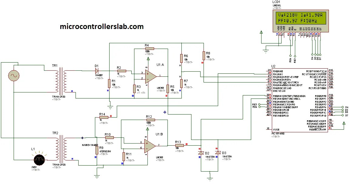
The standard measurements that are performed by a dmm are current, voltage and resistance. Then only it becomes the digital avo meter. Two analog to digital converter channels are used. Pic microcontroller have built in adc’s.
This adc unit basically distinguishes between various types of digital voltmeters which we will discuss later.
Interpret this ac motor control circuit diagram explaining the meaning of each symbol. Block diagram of a dmm using successive approximation register adc. The combination of a resistor in series with pmmc galvanometer is a dc voltmeter. I am showing you a digital multimeter circuit using icl7107.
A basic multimeter schematic circuit diagram capable of measuring voltage, current, resistance of different ranges.
Some feature the measurement of additional properties such as temperature and. Staircase ramp digital voltmeter (also called digital ramp) •the most simple a/d •slow conversion and conversion time depends on the magnitude of input signal. To determine this, connect the meter movement, a potentiometer, battery, and digital ammeter in series. The standard and basic measurements performed by multimeter are the measurements of amps, volts, and ohms.
The figure below shows the block diagram of a typical digital voltmeter.
Internal adc of this ic reads the voltage that to be measured and compare it with an internal reference voltage and converts that into the digital equivalent. The part of the circuit diagram of multimeter, which can be used to measure dc voltage is shown in below figure. Lastly, here is a picture of a digital multimeter. These two channels are used to measure ac voltage and current.
I have already explained components of circuit.
So, it can be used to measure dc. Explanation of various blocks input signal: D/a output time v ax clock period v in t (2n 1) clock period c,max = − × clock comp. Fluke digital multimeters (dmms) are on more tool belts, finding more problems, than any other test tools.
Apart from these, a digital multimeter can also measure temperature, frequency, capacitance, continuity, transistor gains etc.
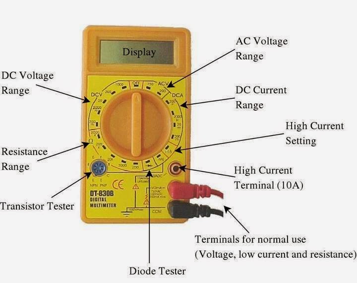
Digital multimeter circuit diagram circuit diagram of digital multimeter is given. Actual assortment and variety of buttons may vary by digital multimeter model. As we can see, the block diagram consists of attenuator with an analogue to digital converter after it. For example, measure dc voltage, acv, dc amp meter, ac amp meter and as the ohms meter, etc.
Circuit diagram and working explanation: