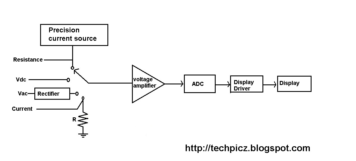
A multimeter can be used to measure electrical functions such as voltage, current, resistance, continuity and some are able to measure electrical frequency. The part of the circuit diagram of multimeter, which can be used to measure dc voltage is shown in below figure. The figure below shows the block diagram of a typical digital voltmeter.
Digital Multimeter Block Diagram Explanation Electronics
Digital multimeter block diagram and explanation maintenance practice question easa part 66 guide.
There are two main types of multimeters.
It is basically the signal i.e. The basic circuit of a digital multimeter is always a d.c. Voltmeter as shown in the fig. A multimeter, shown in figure 1, is a device used to measure two or more electrical quantities.
A counter section is also employed in the circuitry that is usually a decade counter.
Useful components choccy block crystal radio. And next to this signal is processed onto the pulse generator which generates a train of rectangular pulses by using both analog and digital techniques. In a schmitt trigger, the signal is. The basic circuit of one type of analog electronic voltmeter is illustrated in figure 1.
Xdevs com hp 3458a 8 5 digit metrology grade dmm restoration.
Smartphone repair training course learn how to fix. Keithley 7002 instruction manual pdf download. The current is converted to voltage by passing it through low shunt resistance. Bookmark file pdf digital multimeter block diagram and explanation the premier reference for instrument engineers around the world.
It uses digital, analog or both techniques to generate a rectangular pulse.
Omron sysdrive mx series user manual pdf download. Digital multimeter block diagram and explanation glossary of key terminology used in printed circuit board. This adc unit basically distinguishes between various types of digital voltmeters which we will discuss later. The above circuit looks like a multi range dc voltmeter.
The 200 mv module is shown only as a single block.
So, it can be used to measure dc. The combination of a resistor in series with pmmc galvanometer is a dc voltmeter. The signal may be amplified before being applied to schmitt trigger. The block diagram of a simple digital voltmeter is shown in the figure.
Digital multimeter layout • the top portion of the meter contains the digital readout area which displays the measurement value.
Free online calculators for engineers electrical. It is also known as the voltmeter or ohm meter or volt ohm meter. A digital multimeter (dmm) is a measuring instrument used to measure various electrical quantities. It is also called electronic multimeter or voltage ohm meter (vom).
An input attenuator, an electronic amplifier, and an electromechanical voltmeter stage.
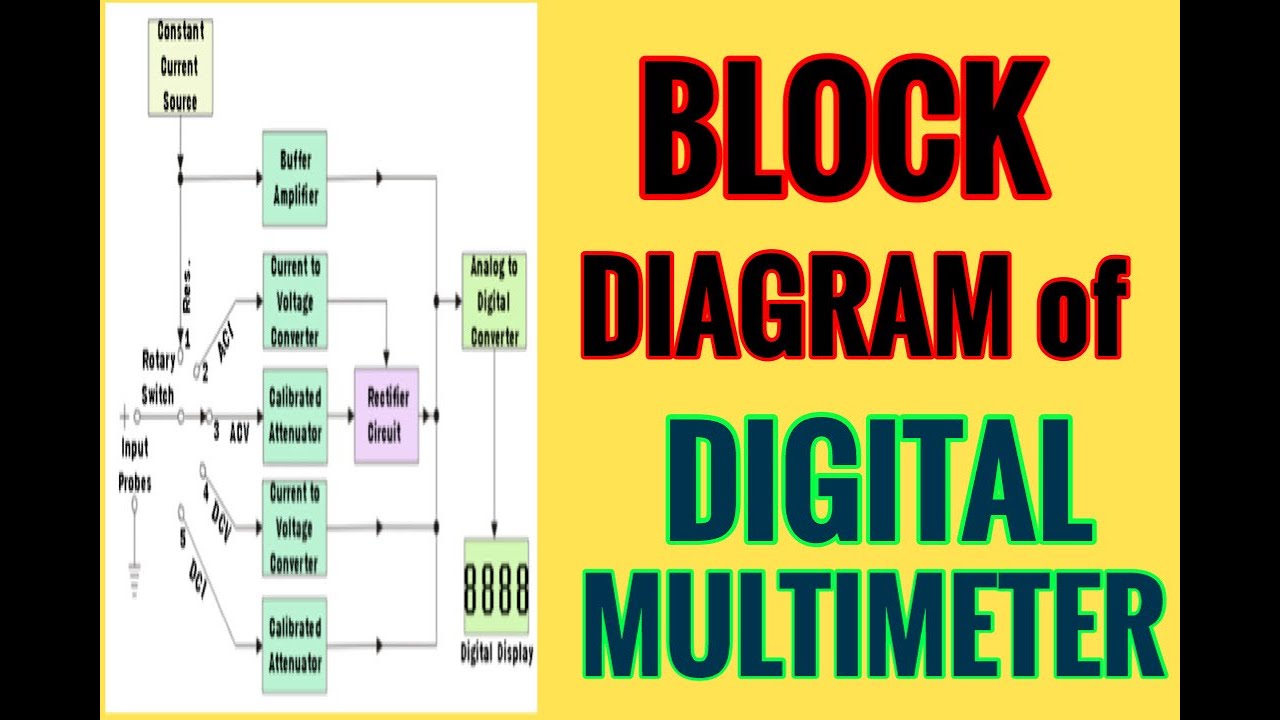
The basic block diagram of a typical digital multimeter is given in the diagram below. Ritter s crypto glossary and dictionary of. How a diode works talking electronics. From the above block diagram, the voltage to be measured is given to the input signal present in the circuit diagram.
Functional block diagram of digital frequency meter contents show working principle of digital frequency meter applications of digital frequency meter working principle of digital frequency meter 1.
Xdevs com hp 3458a 8 5 digit metrology grade dmm restoration. This particular circuit is made up of three stages: Digital multimeter is a test equipment which offers several electronic measurement task in one tool. Apart from these, a digital multimeter can also measure temperature, frequency, capacitance, continuity, transistor gains etc.
The block diagram of 7107 and that of the panel meter are given above to present a clear picture of panel meter, which uses the d.v.m module.
Digital multimeter block diagram and explanation maintenance practice question easa part 66 guide. Although different dmms will use different circuits, the same basic techniques tend to be used from one test instrument to the next. The standard measurements that are performed by a dmm are current, voltage and resistance. The conversion from analog signal to a digital signal in an analog to digital converter is explained below using the block diagram given above.
Ritter s crypto glossary and dictionary of technical.
Working principle of digital voltmeters: Lexikon der mechatronik englisch deutsch fachlexika de. Electronic voltmeter circuit diagram (block diagram) Explanation of various blocks input signal:
Actually it is a voltage source.
• the function switch dial is turned to select the meter’s function. 2/11/2017 working and block diagram explanation of ramp type digital voltmeter(dvm) electricalengineeringinfo | online electrical engineering website andblockdiagramexplanationoframptypedigitalvoltmeter.html 3/4 newer post older post follow the author the decimal number as indicated by the readout is a measure of the value of input. Currents and resistances over several ranges. Lexikon der mechatronik englisch deutsch fachlexika de.
As we can see, the block diagram consists of attenuator with an analogue to digital converter after it.
Digital panel meter block diagram the block diagrams for measuring steady voltage, and alternating voltage are shown above : Block diagram of a dmm using successive approximation register adc Traffic light control electronic project. The digital multimeter is an instrument which is capable of measuring a.c.
The unknown frequency signal is fed to the schmitt trigger.