All multimeters measure ac and dc voltage (voltmeter), ac and dc current (ammeter), and resistance (ohmmeter). It is also known as the voltmeter or ohm meter or volt ohm meter. Working principle of digital multimeter.
Digital Frequency Meter Construction, Working and Its
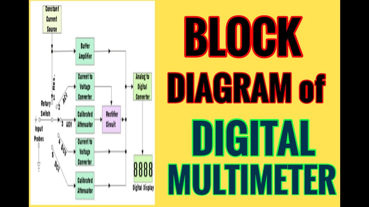
As we can see, the block diagram consists of attenuator with an analogue to digital converter after it.
To the other terminal of the gate, a pulse of
The output of the current to. How does a digital voltmeter work. An input attenuator, an electronic amplifier, and an electromechanical voltmeter stage. Digital multimeter block diagram explanation.
It is basically the signal i.e.
The unknown frequency signal is fed to the schmitt trigger. Working principle of digital frequency meter. And next to this signal is processed onto the pulse generator which generates a train of rectangular pulses by using both analog and digital techniques. The basic block diagram of a typical digital multimeter is given in the diagram below.
Posted on may 19, 2014 by electronic products.
The standard and basic measurements performed by multimeter are the measurements of amps, volts, and ohms. Meter is shown in figure. An aluminum pointer is attached to the coil and bobbin. Then only it becomes the digital avo meter.
The voltage sensor built around a step down element and potential divider network senses both the phase voltage and load voltage.
The coil is wound on an aluminum former or bobbin. Electronic voltmeter circuit diagram (block diagram) • the function switch dial is turned to select the meter’s function. There is an iron cored coil pivoted on two jeweled bearings.
Explanation of various blocks input signal:
Working principle of digital voltmeters: A multimeter is a permanent magnet moving coil galvanometer. First converted to digital form and then displayed on seven segment display. Apart from that, these digital…
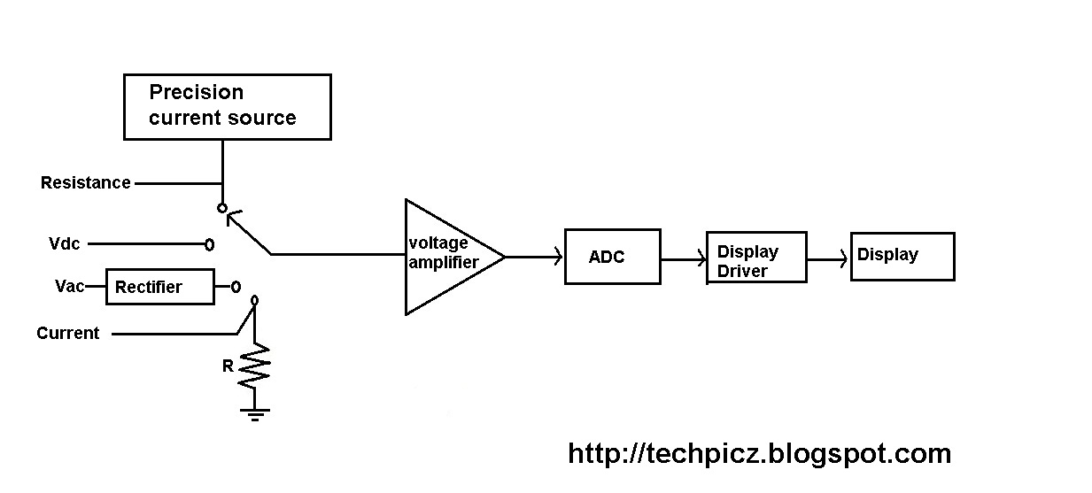
The block diagram of a digital multimeter is shown in the fig.
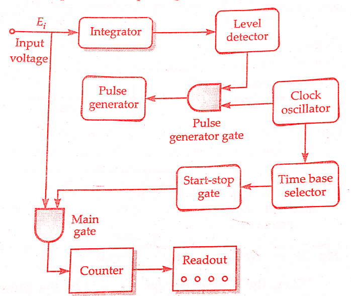
As shown in the block diagram, in a typical digital multimeter the input signal i.e ac or dc voltage, current, resistance, temperature, or any other parameter is converted to dc voltage within the range of the adc. It uses digital, analog or both techniques to generate a rectangular pulse. In order to measure large voltages, potential divider networks can be made on the input of the adc. The signal waveform whose frequency is to be measured is converted into tngger pulses and applied continuously to one terminal of an and gate.
Digital multimeter layout • the top portion of the meter contains the digital readout area which displays the measurement value.
A counter section is also employed in the circuitry that is usually a decade counter. Some can also measure other electrical quantities such as frequency or even. Actually it is a voltage source. Let us assume, that the rpm of a rotating shaft is r.
Block diagram of a dmm using successive approximation register adc.
The signal may be amplified before being applied to schmitt trigger. A digital multimeter (dmm) is a measuring instrument used to measure various electrical quantities. While specifications vary, most dmms can be described with block diagrams. Construction | working principle of multimeter.
And this coil is free to rotate in the field of a permanent magnet.
In general, dmms have a minimum of five typical functions. A digital multimeter (dmm) is an instrument that can measure several basic electrical quantities and shows the measurement with a number in a display. This particular circuit is made up of three stages: A digital multimeter is one that is capable of measuring voltage, current, of alternating current circuits as well as direct current circuits.
This adc unit basically distinguishes between various types of digital voltmeters which we will discuss later.
Digital multimeters and frequency meter. These are voltage and current sensors. Digital tachometer working principle technique employed in measuring the speed of a rotating shaft is similar to the technique used in a conventional frequency counter, except that the selection of the gate period is in accordance with the rpm calibration. Apart from these, a digital multimeter can also measure temperature, frequency, capacitance, continuity, transistor gains etc.
The unknown voltage is applied to the input of the integrator, an output voltage (eo) starts to rise.
They are dc voltage, ac voltage, dc current, ac current, and resistance. Although different dmms will use different circuits, the same basic techniques tend to be used from one test instrument to the next. The following figure represents the digital multimeter block diagram with all the functional blocks. The oscillator output reaches the current to voltage converter through a selectable source resistance r s and the component under test (dut).
The block diagram for a digital meter.
Digital multimeters convert analog signals to digital information. The standard measurements that are performed by a dmm are current, voltage and resistance. The slope of the output voltage (eo) is determined by the. In addition it must have a provision for measurement of resistance also.
The block diagram of a simple digital voltmeter is shown in the figure.
A digital voltmeter (dvm) is truly a voltage measuring unit where unknown analog dc voltage is to be measured i.e. Here, two basic sensors are employed. Here is the working principle of integrating type digital voltmeter (dvm). The block diagram of a digital l.c.r.
From the above block diagram, the voltage to be measured is given to the input signal present in the circuit diagram.
Digital multimeter is a test equipment which offers several electronic measurement task in one tool. Operation flow diagram for operation of a dmm. It consists of a 1 khz oscillator and a current to voltage converter, it is nothing but an operational amplifier. The basic circuit of one type of analog electronic voltmeter is illustrated in figure 1.
Below the digital readout is a black dial, called the function switch.
In a schmitt trigger, the signal is converted into a square wave with very fast rise and fall times, then differentiated and clipped. The cookies that are categorized as necessary are stored on your browser as they are essential. The working principle of a digital voltmeter can be categorized into five functional sections.