Functional block diagram of digital frequency meter contents show working principle of digital frequency meter applications of digital frequency meter working principle of digital frequency meter 1. Use the right ports labeled hi and lo (see fig. Working principle of digital voltmeters:
Digital Multimeter Working Principle Electrical Academia
The basic circuit of a digital multimeter is always a d.c.
Here are some of the important probes in regular use.
Sensitivity to 0.1 microvolt dc. The port panel is where you plug in your test leads. In a schmitt trigger, the signal is. Proposed model of digital multimeter is preferable dueto their accuracy, durability and extra features.
In addition it must have a provision for measurement of resistance also.
Voltmeter as shown in the fig. The block diagram of a simple digital voltmeter is shown in the figure. Adjust the range of the measurement using the level up and down keys hi lo The standard and basic measurements performed by multimeter are the measurements of amps, volts, and ohms.
The unknown voltage is applied to the input of the integrator, an output voltage (eo) starts to rise.
From the above block diagram, t he voltage to be measured is given to the input signal present in the circuit diagram. Apart from that, these digital… If the multimeter reads 1 or displays ol, it's. A pointer is attached with the coil.
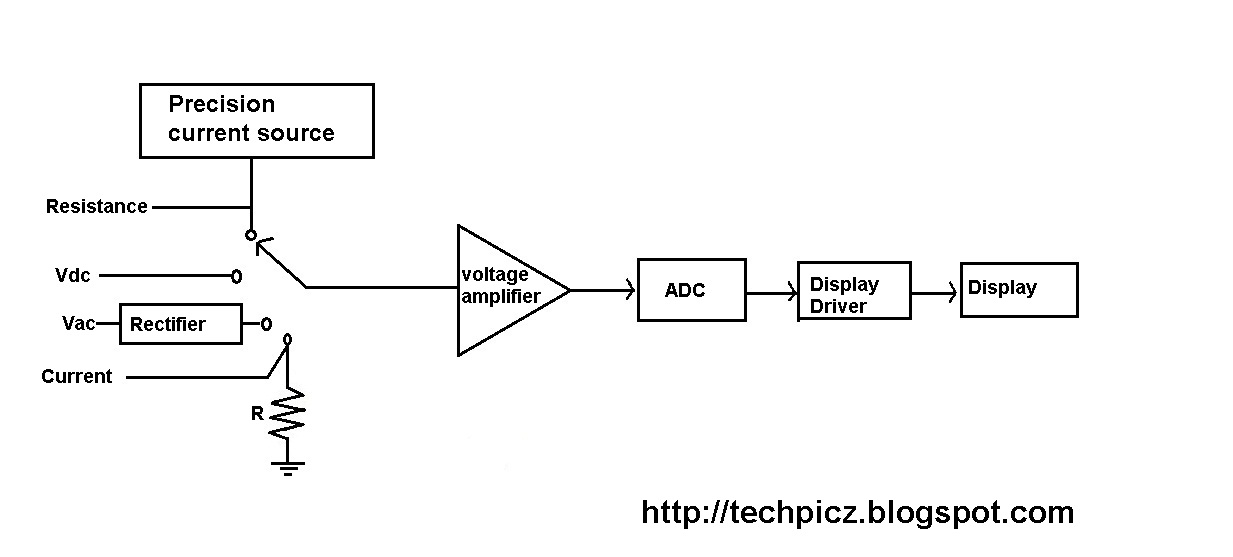
In a digital multimeter the signal under test is converted to a voltage and an amplifier with electronically controlled gain preconditions the signal.
To the left block diagram of a ramp type, digital multimeter working principle at block diagram analog multimeter block diagram the difference between a typical switch and a three way move is one extra terminal or association a 3 way move The basic block diagram of a typical integrating type digital voltmeter ( dvm) is shown in the above figure. It is basically the signal i.e. Posted on may 19, 2014 by electronic products.
The slope of the output voltage (eo) is determined by the.
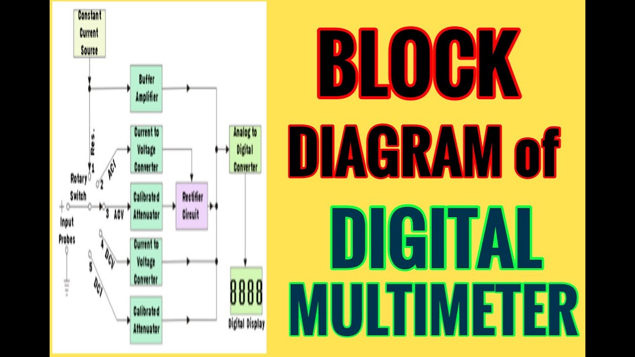
Actually it is a voltage source.it uses digital, analog or both techniques to generate a rectangular pulse. Choose either ac or dc voltage by hitting the ac v or the dc v key 3. Block diagram of digital multimeter. Explanation of various blocks input signal:
There is a diagram of the front of the multimeter given in fig.
• the function switch dial is turned to select the meter’s function. While specifications vary, most dmms can be described with block diagrams. The diagram below explains where the test leads go for specific tests. Since, the analog multimeter is a pmmc types instrument, so when a current is passed through its coil, the coil moves in a magnetic field produced by the permanent magnet.
Banana plugs to crocodile clips;
#electrical_and_electronics_tutorials_in_teluguthe digital multimeter is the most advanced measuring instrument that makes use of modern integrated circuits. Testing a diode with a digital multimeter § digital multimeters have a special setting for testing a diode, usually labeled with the diode symbol. There are different types of probes available for multimeters. All multimeters measure ac and dc voltage (voltmeter), ac and dc current (ammeter), and resistance (ohmmeter).
As shown in the block diagram, in a typical digital multimeter the input signal i.e ac or dc voltage, current, resistance, temperature, or any other parameter is converted to dc voltage within the range of the adc.
Currents and resistances over several ranges. Digital multimeter block diagram explanation. A digital multimeter (dmm) is an instrument that can measure several basic electrical quantities and shows the measurement with a number in a display. A digital multimeter is one that is capable of measuring voltage, current, of alternating current circuits as well as direct current circuits.
In this case, the meter reads 0.97, meaning this resistor has a value of 970ω, or about 1kω (remember you are in the 20kω or 20,000 ohm mode so you need to move the decimal three places to the right or 970 ohms).
In general, dmms have a minimum of five typical functions. The unknown frequency signal is fed to the schmitt trigger. The signal may be amplified before being applied to schmitt trigger. The width and frequency of the rectangular pulse is controlled by the digital.
Block diagram of digital multimeter.
Digital multimeter model 174 general information section i. Digital multimeters convert analog signals to digital information. Digital multimeters are more accuracies, higher input multimeter safety when making a meter selection look for a tester that is independently certified to some safety standard, ul, iec, csa. Working principle of digital multimeter.
Some can also measure other electrical quantities such as frequency or even.
It is also known as the voltmeter or ohm meter or volt ohm meter. Then only it becomes the digital avo meter. The diode should conduct and the meter will display a value (usually the voltage across the diode in mv, 1000mv = 1v). Dmm controls and connection ports.
The meter will read one of three things,0.00, 1, or the actual resistor value.
These cables are used for connecting large wires or pins on a bread board as shown in figure 10.15. And next to this signal is processed onto the pulse generator which generates a train of rectangular pulses by using both analog and digital techniques. The digital multimeter is an instrument which is capable of measuring a.c. Here is the working principle of integrating type digital voltmeter (dvm).
Figure 10 to measure voltage:
Below the digital readout is a black dial, called the function switch. Connect the dmm in parallel as shown in fig. Digital multimeter layout • the top portion of the meter contains the digital readout area which displays the measurement value. Digital multimeter is a test equipment which offers several electronic measurement task in one tool.
They are dc voltage, ac voltage, dc current, ac current, and resistance.