The mode selector switch has five positions. Block diagrams are made similar to flowcharts. In smartdraw, you'll want to start with a block diagram template that already has the relevant.
5MP OV5640 Arduino Based Camera
The conversion from analog signal to a digital signal in an analog to digital converter is explained below using the block diagram given above.
Opening in the camera to allow the light from the object to enter the camera.
It is divided into component and sub system as and lay them out in them in the system diagram. Please subscribe to electronics post channel if you like my tutorials. In adc, the conversion of the signal from analog to digital can be explained through the above block diagram. Stuff like filters and converters add to the complexity of a system.
Fig.1 shows the block diagram of a general communication system, in which the different functional elements are represented by blocks.
The other input terminal is a common terminal, generally referred as ground or negative terminal. The fig (a) shows one possible block diagram of a digital camera. To make a block diagram in wondershare edrawmax, you can follow the instructions given below: View finder and focussing ring:
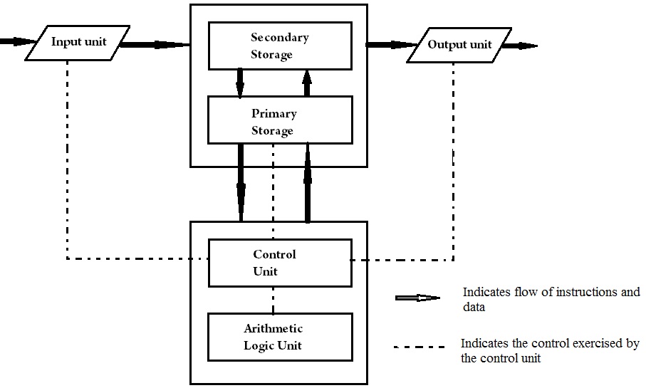
You will want to create blocks, often represented by rectangular shapes, that represent important points of interest in the system from input to output.
Disadvantages of a digital signal processing system. A digital camera is used for record and store the images or photo in a digital form. It uses blocks connected with lines to represent components of a system. For your information i used to understand an equipment block diagram first before i go into the schematic and analyze the circuit functions.this is the first step if you wants to venture into new electronic equipment repair.
As we saw in the block diagram above, there are a lot of elements preceding and following a digital signal processor.
The essential components of a communication system are information source, input transducer, transmitter, communication channel. The sample block function is to sample the input analog signal at a specific time interval. How ordinary film cameras work. Lines connecting the blocks will show the relationship between these components.
Budget digital camera $250 or under.
A block diagram is a drawing illustration of a system whose major parts or components are represented by blocks. A film.a film is a long spool of flexible plastic coated with special chemicals (based on compounds of silver) that are sensitive to light. This input is red ur screen that measures changes in capacitance in the output x and y coordinate or more touches. Here, the crt employed in the circuit displays the data stored in the electronic digital memory.
Pick a block diagram template start wondershare edrawmax on your computer, ensure that new is selected in the navigation pane at the left, confirm that basic diagram is selected in the diagram types list in the middle, and click to select block diagram.
Digital camera and camcorder, bird attracting device, wireless data transmission module, power supply with solar. Block diagram of digital storage oscilloscope. System layout of digital camera. While there are still dedicated.
The block diagram shows that the input terminal is connected to a mode selector switch.
In this video, i have explained block diagram of digital communication system by following outlines:0. We use block diagrams to visualize the functional view of a system. A digital camera is very use. We need the input tell the smart phone to allow the camera application to take the picture.
Circuit schematics diagrams of digital camera.
As the data in memory is stored in digital form, the signal is reconstructed in analog form in order to be displayed on the screen of crt. In the sample block, the analog signal can be. Block diagram of digital audio recorder. A digital signal processor is made up of transistors.
The cpu is the main processor is also connected with the various other processors.
Digital camera includes various types of memories like dram, memory card, flash memory with controller etc. Finally, the last block like encoder changes the discrete amplitude into a binary number. Here’s a block diagram of a digital lcd tv and if possible you may print it out for future use. Likes ( 75) dislikes ( 42)
My camera looks as if the lens is blocked on the left side.
There is nothing that seems to be visibly blocking the lens but it. To properly focus the object before the photograph is clicked. Camera is an instrument which gives a permanent image of the object on a film. Optional system components can be:
These blocks are joined by lines to display the relationship between subsequent blocks.
A digital camera is a camera that captures photographs in digital memory.most cameras produced today are digital, largely replacing those that capture images on photographic film.digital cameras are now widely incorporated into mobile devices like smartphones with the same or more capabilities and features of dedicated cameras.