The circuit is simple low cost and can be even assembled on a veroboard. The transfer characteristics of an ideal inverter is shown below. By doing simple modification you can also convert 6v dc to 230v ac or 110v ac.
Full Bridge Inverter with MOSFET and IR2110 gate driver
Inverter circuit diagram using sg3525 and.
Sine wave inverter circuit diagram with complete step by step program and coding, in this article i will discuss how to use push pull converter, sinusoidal pulse width modulation, h bridge and low pass lc filter to make pure sine wave inverter circuit diagram.
100watt inverter circuit inverter circuits are accompanied by the easiest circuits to produce develop for newbies here is the circuit diagram of a genial 100 watt inverter using ic cd4047 and mosfet irf540. Pwm inverter circuit diagram using ic sg3524 and mosfet. That can withstand currents up to 18a. N1, n2, n3, n4 not gates from the ic 4049 are arranged as a voltage doubler circuit, which generates about 20.
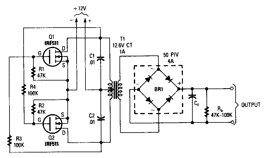
So, in today’s tutorial, we will take a look into a step by step process on how you can build a simple 12v to 220v inverter circuit using two irfz44 mosfets.
If the circuit is fully functional with maximum power of 12v x 18a = 216 watts. Inverter circuit diagram using sg3525 and mosfet a 250w pwm inverter circuit built around ic sg3524 is shown here. Simple 12v to 230vac inverter circuit mosfet diy electronics. According to properties listed in the table of figure 2.
Inverter circuit diagram using mosfet with 1399x1071 resolution admin / diagram / 1 views.
Twitter facebook whatsapp google+ linkedin pin it. We use q1, q2 is the mosfet acts as a power output. Inverter circuit is one of the fundamental building blocks in digital circuit design (not to be confused with a power inverter). Determine the vpp and dc offset setting required for function generator.
Find every electronics circuit diagram here, categorized electronic circuits and electronic projects with well explained operation and how to make it procedure and then new circuits every day, enjoy and discover electronics.
The inverters can be applied directly to the design of logic gates and other more complex digital circuits. Sine wave inverter circuit description. Use edrawmax for circuit diagram creation. Inverter circuits are among the easiest circuits to build for newbies.
As 200 watts inverter circuit.
Simple mosfet inverter circuit diagram. 220v inverter circuit using irfz44 mosfet simple 100w with fet irf540 12v to 230vac rangkaian dc ke ac panduan 500w power circuits electrical4u 555 h bridge 4 n what is an diagram 7 you can high voltage easy 150 w full 100 watts working and for newcomers watt 500. Use the pair of nmos and pmos gates on the right side of the ald1105 ic. To ensure 100% safety for the mosfets in the charging mode and while using the body diodes with the transformer ac, the mosfet gates must be held at the ground potential, and completely.
For a vdd of 3v, 5v, 7v, sketch the input waveforms required to test the functionality of the cmos inverter.
Image of the pcb layout of this high power inverter circuit diagram is given. It contains all the necessary features and libraries that will suffice you in your diagram making. The pcb layout of this circuit diagram is below. Simplest inverter using hybrid mosfets and igbts with unipolar pwm to scientific diagram.
1 shows the sine wave inverter circuit of the
This voltage should be suitably derived from one of the batteries which are being incorporated for driving the inverter circuit. 21 posts related to inverter circuit diagram using mosfet. Simple 100w inverter circuit full of zip and circuit diagram. This is the complete circuit diagram of a 1250va/24v mosfet inverter with battery charger.
How to make inverter ( 100 watt 200 watt 300 watt 500 watt ) using sg3524 ic & p55nf06 , irfz44n or irf3205 mosfetin this video tutorial i have attached an i.
All you need is a good soldering skills , a little bit […] This simple low power dc to ac inverter ( dc to ac converter) circuit converts 12v dc to 230v or 110v ac. The circuit is simple low cost and can be even assembled on a veroboard. The following diagram shows a practical design set up for implementing mosfet body diodes as a rectifier for charging an inverter battery, with relay changeover switches.
Simple low power inverter circuit | 12v dc to 230v or 110v ac | diagram using cd4047 and irfz44 power mosfet.
High side mosfet driver circuit tri state power diagram all gate isolated for pwm and igbt circuits 3 drivers what why por cheap in circuitlab use tc4420 simple h driving p channel project half bridge drive guidelines microchip technology discrete using single output n stepper motor switchcraft l6498 voltage low safe operation area 4 7 2 design. This software is used for diagram making.