Image of the pcb layout of this high power inverter circuit diagram is given. This basic inverter circuit can handle up to 1000watts supply depends the t1, t2 and transformer used. The inverter constructed converts 12v dc to 220v ac.
Blog Kang Zen Rangkaian Power Inverter 500W220V
They are durable and sustainable to offer consistent.
This is the circuit diagram of high power 1250va digital inverter with charger.
You can select from the existing circuit diagram of inverter with battery charger models on the site or go for completely customized versions of these products. Your email address will not be. Then at the input, we must have at least 18.3v at 12v because of 12v*18.3 = 220v*1. Schematic diagrams inverter tbe 1500 watt wiring diagram line wiring diagram.
12v dc to 220v ac inverter with battery charger circuit diagram.
This is a cpomplete inverter circuit diagram with charger and overload function. Inverter with charger circuit diagram (4 in 1) leave a comment / inverter circuit, uncategorized 12v dc to 220v ac inverter with battery charger circuit diagram , automatic dc fan controller circuit, simple inverter circuit diagram, low cost 500w inverter circuit using 2n3055, 220v 50w low power inverter circuit, what is not gate (inverter) Figure 1 shows the main circuit diagram of the inverter circuit. This simple low power dc to ac inverter (dc to ac converter) circuit converts 12v dc to 230v or 110v ac.by doing simple modification you can also convert 6v dc to 230v ac or 110v ac.
The inverter prototype was designed by using pulse width modulation (pwm) signal generated by egs002 module, combined with dc voltage source,.
Ups inverter diagrams pdf free 3000w power 12v to 230v digital circuit diagram 4 simple uninterruptible supply sinewave using pic16f72 homemade solar m 100 watt offline engineering projects electronic abc home facebook sine wave build 200w 500 with battery circuits 2000w homage schematic microtek how an works. Leave a comment cancel reply. 220v 50w low power inverter circuit. Microtek inverter circuit diagram pdf electrical learner.
The basic formula is p=vi and between input output of the transformer we have power input = power output.
It can be used as inverters for home needs to enable light loads (electric bulb, cfl, etc) at the time of electricity failure. Inverter section | 3000w inverter with inbuilt charger using at89c2051: On off timer circuit diagram using 555. For example, if we want a 220w output at 220v then we need 1a at the output.
220v 50w low power inverter circuit.
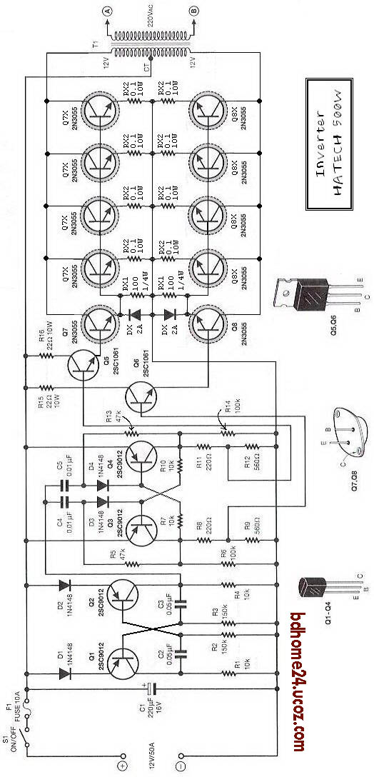
An inverter is a system which is capable of converting dc voltage from a battery into ac voltage. Low cost 500w inverter circuit using 2n3055. Inverter circuit 500w 12v to 220v eleccircuit com. It consists of an oscillator section using 8v dc to produce 50hz sine wave.
This is the circuit diagram of high power 500w inverter.
You can use these 24v pure sine wave power inverter circuit diagram in your homes, hotels, offices, or any other commercial properties where power requirement is costly and crucial. This is the circuit diagram of 500w high power inverter market kit. These pulses drive the mosfets alternately which in turn saturate the transformer by switching the battery voltage in it. Egs002 inverter circuit diagram pdf egs002 inverter circuit diagram pdf.
This section converts 24v dc to 220v ac and also charges the battery connected.
Marine inverter charger wiring diagram. The circuit will convert 12v dc to 120v ac. Low cost 500w inverter circuit using 2n3055. 1500w inverter full schematics and pcb 1500 watt pwm sinewave circuit homemade projects 500w 12v to 220v eleccircuit com 2000w power with diagrams gohz 12 volt 1000 design process tbe t12p1000w pure sine wave w usb input lazada ph service manual rar schematic.
The inverter section can be easiy recognized in the diagram, r1 to r6, including the t1 and t2 forms a general astable multivibrator circuit for producing the required 50 or 60 hz pulses.
These circuit diagram of inverter with battery charger are equipped with the latest technologies and come with distinct power capacities to serve your purpose with ease. Leave a comment / inverter circuit / by admin. This is component layout or pcb layout of this 500w inverter circuit. Inverter circuit diagram 5000w free download 2022 by kaia.schoen.
Find the besttemplates at vincegray2014.
500w high power inverter circuit diagram. You can construct this circuit of a simple inverter at a cheap. Circuit diagram pcb layout/component layout related post microtek digital inverter circuit switch on delay timer circuit stereo audio amplifier circuit using. Below is also component layout/pcb layout of this schematic diagram.
Cp2102 usb to ttl copy.