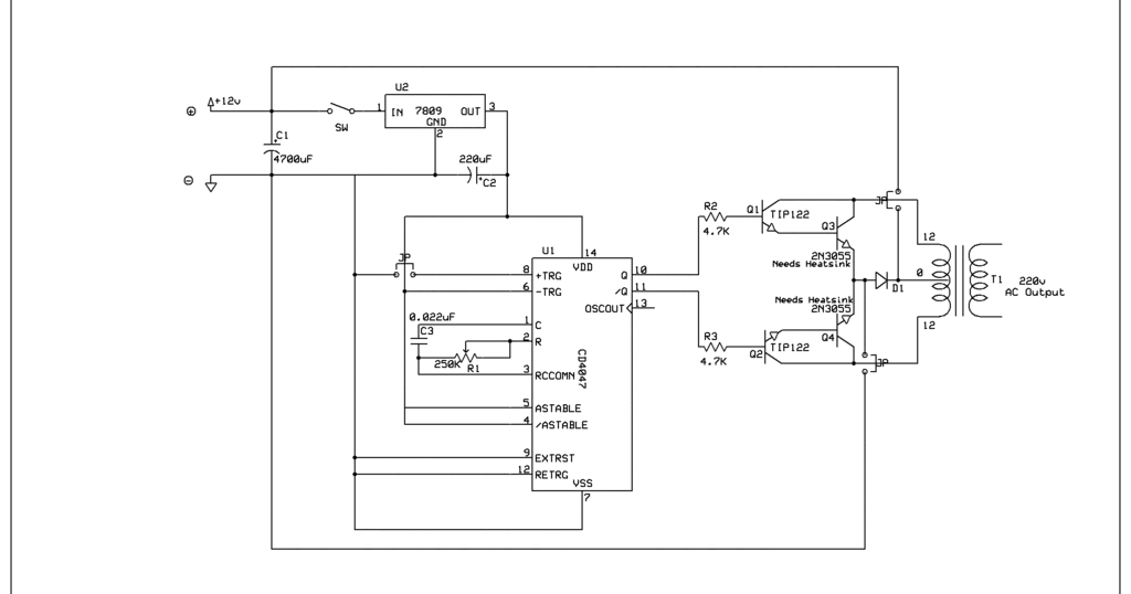
The alternating current is a current that consistently changes its magnitude with respect to time. As, the usual transformer cannot work on dc, so we have to make voltage and currentchangingw.r.ttime. Circuit diagram for cd4047 inverter:
100 Watts Inverter Circuit using CD4047 & IRF540
Furthermore, this ic is easy to configure for both modes and requires few external components to operate.
Hi, today i'll show you a simple yet powerful inverter with the popular cd4047 ic and the irf1404 power mosfets.
The ic cd4047 acts as a switching pulse oscillating device. It doesn’t include battery charging circuit which is present in most of the inverters. Find every electronics circuit diagram here, categorized electronic circuits and electronic projects with well explained operation and how to make it procedure and then new circuits every day, enjoy and discover electronics. Inverter circuit diagram using cd4047 simple inverter circuit using cd4047 working.
The operating frequency of astable multivibrator is set to 50hz.
It works by charging a capacitor (c2) through a resistor (rv1) as in every astable multivibrators. Cd4047 output current gate driver? Sine wave inverter circuit description. And more importantly, it has a duty cycle at 50% in a symmetrical standard, no need for additional equipment.
This current flows only in one direction.
In astable mode, it operates by charging a capacitor using a valuable resistor that is mainly used to adjust the output frequency near 50hz. Here it is wired in astable mode. The inverter circuit is built around ic cd4047 which is wired as astable multivibrator. Click the image to enlarge.
Inverter circuit are very much helpful to produce high voltage using low voltage dc supply or battery.
Your email address will not be. They are pin 10 and 11 respectively. However, the resistors connected to pin 2 are rated at 0.5w and the ic has a maximum power dissipation of 500 mw. I haven't looked at the circuit.
Cd4047 simple astable multivibrator circuit.
It is therefore suitable for generating a set frequency in inverter circuit. The cd4047 ic is a low power cmos logic based multivibrator circuit ic. I am building this solar powered inverter: Ti, alldatasheet, datasheet, datasheet search site for electronic components and semiconductors, integrated circuits, diodes, triacs and other semiconductors.
Cd4047 requires only 2 devices, resistor, and capacitor only.
I want to keep the efficiency of the system as high as possible. Variable resistor (rv1) is provided for. It can operate either in the monostable or astable mode. It can handle 3000w with proper cooling.
Inverter circuit diagram using cd4047 simple inverter.
Four cd4047 inverter circuit 60w100w 12vdc to 220vac. In the previous post we discussed the main specifications and datasheet of the ic 4047 where we learned how the ic could be configured into a simple inverter circuit without involving any external oscillator circuit. Looking for ltspice modules of cd4047 and mc14528b. Cd4047 is a low power ic capable of operating in either in astable or monostable mode.
1000 watts inverter circuit diagram 500 watt inverter circuit diagram this is a simple 500 watt inverter circuit inverter ups 1000 watt inverter 24 v 45 a 1000 w 20 to 26 500.
In this article we carry on the design a little ahead and learn how it can be enhanced into a pure sine wave inverter circuit using a couple of. Simple inverter circuit using cd4047 and uln2003. Cd4047 is a low power inverter that comes with an ability to operate in both states: Leave a reply cancel reply.
Essentially all the current just flows through the mosfet.
The power mosfets (the two irfz44) are directly driven by the q and q’ output of cd4047. Cd4047 working in monostable and astable mode.


