The cd4047 ic is a low power cmos logic based multivibrator circuit ic. Try 555 and mosfet inverter circuit. Here a simple inverter circuit design projected in order to avoid complex pure sine wave inverter and pwm inverter for the low voltage applications.
Four CD4047 Inverter circuit 60W100W 12VDC to 220VAC
If the focus is on the astable multivibrator circuit.
This power can be used for electronic appliances like television, mobile.
In this article we carry on the design a little ahead and learn how it can be enhanced into a pure sine wave inverter circuit using a couple of. Inverter circuits are provides ac power output using available dc voltage from battery, some times we need low power output enough to drive a small electric light bulb or something those are not require pure ac power. They are pin 10 and 11 respectively. Submitted by dataxheet on 21 february it needs an external resistor to be connected between pin 1 and 3 to determine the output.
It can handle 3000w with proper cooling.
Simple inverter circuit using cd4047 and uln2003 it needs an external resistor to be connected between pin 1 and 3 to determine the output pulse width in monostable mode. Simple 40 watt inverter circuit using ic cd4047b. Cd4047 requires only 2 devices, resistor, and capacitor only. The operating frequency of astable multivibrator is set to 50hz.
The formula for finding the value of frequency mathematically at pin 11 and 10 is:
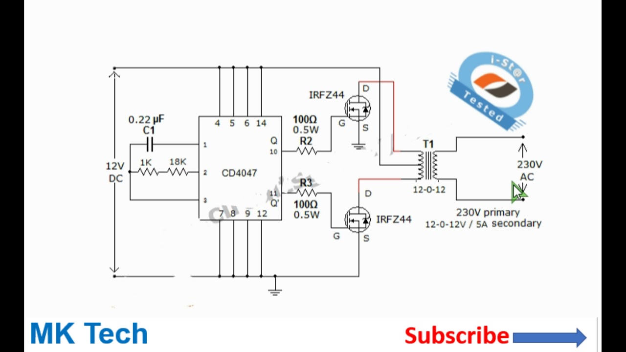
Hi, today i'll show you a simple yet powerful inverter with the popular cd4047 ic and the irf1404 power mosfets. The inverter circuit is built around ic cd4047 which is wired as astable multivibrator. Submitted by admin on 21 february message 5 of discussion in ‘ general electronics chat ‘ started by uceesdpaug 13, message 7 datashee for determining output frequency in astable mode it needs a capacitor to be connected between pin 2 and 3. Furthermore, this ic is easy to configure for both modes and requires few external components to operate.
Cd4047 working in monostable and astable mode.
Simple inverter circuit using cd4047 and uln2003. The ic cd4047 acts as a switching pulse oscillating device. Inverter circuits simple transistor diy inverters working. In the previous post we discussed the main specifications and datasheet of the ic 4047 where we learned how the ic could be configured into a simple inverter circuit without involving any external oscillator circuit.
Simple inverter circuit using cd4047 and uln2003 we can use the ic in both astable and monostable mode, for making different circuit.
Your email address will not be published. Astable multivibrator working using ic cd4047. Simple inverter circuit using cd4047 and uln2003 this website uses cookies to improve your experience. Cd4047 is a low power inverter that comes with an ability to operate in both states:
It is better than 555 timer ic.
We use cd4047 because the output is 50% duty cycle. Simple inverter circuit using cd4047 and uln2003. • high voltage type (20v rating). By varying the vr1 resistor value we can change the frequency and voltage range of output ac supply, for to simplify the design there is no switch, fuse and mov metal oxide varistor and this circuit involved in producing high ac voltage that.
In astable mode, it operates by charging a capacitor using a valuable resistor that is mainly used to adjust the output frequency near 50hz.
It can operate either in the monostable or astable mode. Square wave inverter using cd4047,lm358,2sc1061,2n3055. The circuit built based ic cd4047 to generate sine wave signal 50hz and then the power transistor 2n3055 will boost the signal so that the signal have high power high electric current. Ic cd4047 will work in the astable multivibrator.
It is therefore suitable for generating a set frequency in inverter circuit.
An inverter is an electrical device that converts direct current (dc) to alternating current (ac). The power mosfets (the two irfz44) are directly driven by the q and q’ output of cd4047. True and complemented buffered outputs. The converted ac can be at any required voltage and frequency with the use of appropriate transformers, switching and control circuits.
Input 12vdc from car battery to output 220v ac 50hz or 60hz at square wave signal.
Simple 100w inverter circuit introduction inverter is a small circuit which will convert the direct current (dc) to alternating current (ac). 555 is a timer ic which is used to generate time delay. Learn 555 timer works as oscillator. Inverter circuit are very much helpful to produce high voltage using low voltage dc supply or battery.
And more importantly, it has a duty cycle at 50% in a symmetrical standard, no need for additional equipment.