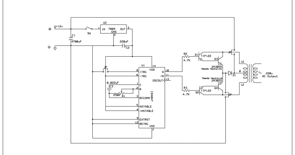
And more importantly, it has a duty cycle at 50% in a symmetrical standard, no need for additional equipment. It can handle 3000w with proper cooling. Lets move into the working of this simple inverter circuit.
CD4047 Power Inverter 12V to 220V DCAC 500Watt! YouTube
The operating frequency of astable multivibrator is set to 50hz.
In the previous post we discussed the main specifications and datasheet of the ic 4047 where we learned how the ic could be configured into a simple inverter circuit without involving any external oscillator circuit.
If the focus is on the astable multivibrator circuit. Pv solar inverter circuit diagram. March 26, 2018 at 7:37 am. It can operate in the monostable mode or astable mode.
Inverter circuits are among the easiest circuits to build for newbies.
This dc to ac inverter circuit work based on unstable multi vibrator does. The heart of this circuit is a cd4047 ic which is wired as astable multivibrator here. Cd4047 requires only 2 devices, resistor, and capacitor only. Cd4047 simple astable multivibrator circuit.
Low cost 500w inverter circuit using 2n3055.
Click the image to enlarge. Hi, today i'll show you a simple yet powerful inverter with the popular cd4047 ic and the irf1404 power mosfets. Sine wave inverter circuit description. It uses 2 power irfz44 mosfets for driving the output power and the 4047 ic as an astable multivibrator operating at a frequency of around 50 hz.
The inverter circuit is built around ic cd4047 which is wired as astable multivibrator.
The circuit is simple low cost and can be even assembled on a veroboard. 11 thoughts on “220v 50w low power inverter circuit” my sources. We need to provide ac input power to those circuits, then only we can. Basically, cd4047 is the 14 pin ic with having very low power consumption.
The only purpose of this ic in the circuit is to generate a duty cycle of 50%.
It doesn’t include battery charging circuit which is present in most of the inverters. Software like edrawmax has all features to make a perfect circuit diagram. Variable resistor (rv1) is provided for. 1000 watts inverter circuit diagram 500 watt inverter circuit diagram this is a simple 500 watt inverter circuit inverter ups 1000 watt inverter 24 v 45 a 1000 w 20 to 26 500.
In this article we carry on the design a little ahead and learn how it can be enhanced into a pure sine wave inverter circuit using a couple of.
Circuit diagram for cd4047 inverter: It can be used to power up to 100w. To drive the output coming from an ic, two irf540 mosfets are used. Inverter circuit diagram using cd4047 simple inverter.
It is therefore suitable for generating a set frequency in inverter circuit.
As, the usual transformer cannot work on dc, so we have to make voltage and currentchangingw.r.ttime. What is not gate (inverter) simple led flasher circuit with 555 timer. You must use a battery and battery charger to implement this inverter circuit. Inverter circuit gives alternating current (ac) output from battery power source, but the battery requires constant dc supply to get charge, so the every inverter circuit contains rectifier and battery charger segment.
This circuit constructed in three simple stages, the first one is multivibrator stage by using ic cd4047, it produce free running astable pulse with high peak voltages, and then second stage is power switching stage using ic uln2003 (seven darlington array) it handles 500ma current and best suitable for.
Furthermore, this ic is easy to configure for both modes and requires few external components to operate. Since the mosfet is a high switching. Simple inverter 12v to 220v with. It can operate either in the monostable or astable mode.
I don’t believe i’ve read anything like this before.
It is famous for making pulse generator and timer. The cd4047 ic is a low power cmos logic based multivibrator circuit ic. The power mosfets (the two irfz44) are directly driven by the q and q’ output of cd4047. And current 3a up for power output than 100w.
My sources you are so cool!
Simple inverter circuit diagram 12v to 220v. The cd 4047 ic is configured in this 12 volt to 220 volt inverter with the aid of several components like. Cd4047 is a low power ic capable of operating in either in astable or monostable mode. The circuit uses the cd4047 ic which works can work in astable or monostable mode.
Here it is wired in astable mode.
It works by charging a capacitor (c2) through a resistor (rv1) as in every astable multivibrators. Circuit diagram for cd4047 inverter click the image to enlarge the circuit is simple ic cd4047 drives the two mosfets which are in push pull configuration as the usual transformer cannot work on dc so we have to make voltage and currentchangingw r ttime. This will help in meeting up the energy demands, power failures and to places where the wiring is not possible. Input 12vdc from car battery to output 220v ac 50hz or 60hz at square wave signal.
In this circuit, ic cd4047 is chosen as a heart of unstable multivibrator, because this ic type gives a complementary output that has opposite phase to another ( pin 10 and 11 as seen in figure 1), and has 50 % duty cycle that satisfy to generate a pulse for inverter.
Inverter circuit diagram using cd4047 simple inverter circuit using cd4047 working.


