Sketch the quantitative energy grade line and hydraulic grade line. Then you can use the pump duty equations in order to work out what power your pump needs to be in order to deliver 6 bar at the nozzle at your required velocity. Assume head lost in the 6 inch (152 mm) pipe to be five times its velocity head while the head lost in the 4 inch (102mm) pipe to be twelve times its velocity head.
Solved Water Flows Out Through A Set Of Thin, Closely Pac
Find the flow rate when pump develops an 80 ft (24.4 m) head.
If the other end of the pipe is a pipe anchor, you need a bellows expansion joint or a different routing that has more flexibility (changes in direction) to allow the pipe to move.
Find the flow rate when the pump develops 30 m head. Friction head loss is expressed by 5v^2/2g and 10v^2/2g for 3 cm and 2 cm diameter pipes, respectively, where v is the velocity in the corresponding pipe. Where p is your pressure, f is the friction factor, l is the length of your pipe, d is the diameter, rho is the density of water and v is the flow velocity. Pipe stress engineers are very familiar with these criteria.
Water from a supply having a total head of 100 ft is used in the jet of an ejector, shown in fig.
Allowable nozzle loads for equipment such as heat exchangers, pumps, and vessels. 1, which gives the methodology that should be followed to avoid these types of potential mechanical pump problems. This helps to eliminate the side loading of the pump impeller and creates uniform pump axial bearing loading. The nozzle can be of.
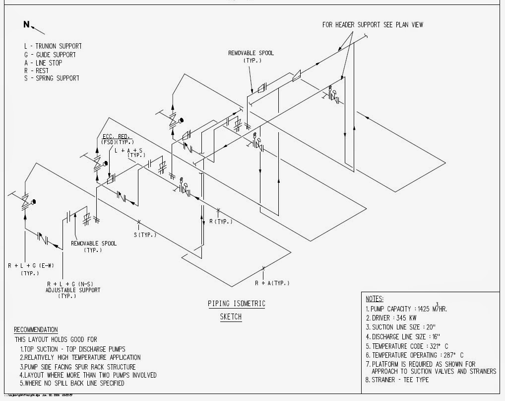
Include 5 to 10 pipe diameters of straight run pipe between the pump inlet and elbow.
Find (a) flow rate and (b) pump horsepower,… a: A pipeline with a pump leads to a nozzle as shown. Find the flow rate when pump develops an 80ft (24.4m) head. The nozzle area of the jet pipe is 0.05 ft2 and the annular area of the suction line at section 1 is 0.5 ft2.
Request pdf | allowable piping imposed nozzle loads on pumps of large diameter nozzles | piping imposed loads are external forces and moments acting on pump suction and discharge nozzles.
Assume head loss in the 150 mm pipe to be five times its velocity head while the head loss in the 100 mm pipe to be twelve times its velocity head. The water surface in the reservoir 1 is at elevation 30 m, the pipe intake 2 and 3 at elevation 25 m and the nozzle 4 and 5 at elevation 0. Pump shall be placed in such a manner that the suction nozzle elevation is always below the vessel or tank nozzle elevation and suction pipe shall be routed to prevent any pockets in the line. Decreased mean time between repair or failure.
Flowchart for use of iso/hi pump.
P2.26, in order to lift 10 ft3/s of water from another source (at a lower level) that has a total head of −5 ft. Find the flow rate when the pump develops a head of 80 ft, given that we may express the friction head loss in. A.) compute the flow rate. The pump adds energy to the water at a rate of 40 ft.lb/lb and the total head loss is 56 ft •if the water pressure at the pipeline entrance is
Eliminate elbows mounted on or close to the inlet nozzle of the pump.
The reservoir on the left has a water level of 70 ft. Δ p = f l d ρ v 2 2. A pipeline with a pump leads to a nozzle as shown below. Determine the loss of head in the pipeline and nozzle.
A pipeline with a pump leads to a nozzle as shown below.
The iso/hi pump piping work group developed the flow chart shown as fig. Problem reservoir a supplies water to a nozzle having a diameter of 80 mm which discharge water 40 m below the reservoir water level at a. Otherwise, as you've already shown, a small amount of growth (with nowhere to go) results in an extremely large force. You have 25ft of straight piping going to a pump suction nozzle.
Eliminate potential for air entrapment in the suction piping
Pump shall be located as close to the source of suction in order to minimize pressure drop in the system. 1 answer to in a firefighting system, a pipeline with a pump leads to a nozzle as shown on the next page. And the 3 in diameter jet is at 80 ft. The allowable nozzle loads are based on the stress induced in the pressure containing device, or minimizing deflection of equipment casings (to avoid damage to the moving parts inside the equipment).
In a fire fighting system, a pipeline with a pump supplies water to a nozzle.
22 m 100 mm 150 mm p el. E 80' (24.4 m) a pipeline with a pump leads to a nozzle as shown. A pipeline with a pump leads to a nozzle as shown, find the flow rate when pump develops a 24 m head. B.) find the pressure head at the suction side
(a) compute the flow rate (b) sketch the energy grade line and hydraulic grade line, and (c) find.
A pipeline with a pump leads to a nozzle as shown. A pipeline with pump head added by the pump, hp =. •water is pumped through a pipeline at a rate of 130 cfs.


