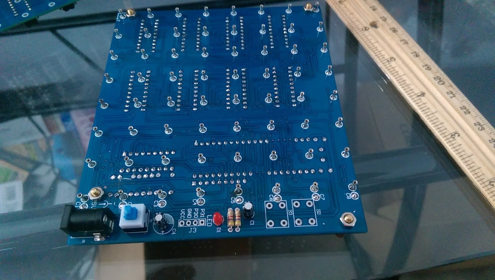
It is designed for entry level hobbyist who wants to take on the challenge to build a bigger cube rather than settle for a 4x4x4 or 5x5x5 led cube. 2) run a solder trace between the emitters of all 16 transistors. The front of the cube will be the flat face of an 8×8 panel with the horizontal anode rails facing forward.
8x8x8 LED Cube PyroElectro Schematic PyroElectro News
Upgraded version diy wifi app 8x8x8 3d light cube kit red blue green led mp3 music spectrum 35 reviews cod upgrade deals.
By hand or with the led in the jig and the anode on the right, bend the cathode 90°.
8 * 8 * 8 = 512 also, because of the currents per leds, you will need a transistor to control the leds axis with enough. It is possible to use 74hc595 for a led cube. Draw a table (7x7) with squares of 2 centimetres each sides. Fourth,start burning,when click 'isp programming',at the same.
Creating an 8x8x8 3d led cube:
This is the first step in preparing the fixture. How to build 8x8x8 led cube diy kit. I’ve just finished building my 8x8x8 led cube diy kit. How to build an 8x8x8 led cube 1) start by placing all 16 transistors on the pcb and soldering each of their pins.
In a 8x8x8 led cube we have 8 anode layers and 64 cathode columns.
Eight red, eight green, and eight blue). Cathode connections will be vertical (24 per panel: A matrix is 2 dimentions = x and y so a cude need 3 dimentions = x , y , z so one chip controlling x, one chip controlling y and one chip controlling z. Creating an 8x8x8 3d led cube:
3d light cube kit 8x8x8 blue led mp3 music spectrum diy electronic kit 188 reviews cod.
Creating an 8x8x8 3d led cube: Creating an 8x8x8 3d led cube: It was a lot of fun and the cube works perfectly. Given the fact that the whole circuit functions at 5v, this means that the resistors between the anode layers and the ground will generate a total current consumption of 8*5 ma = 40 ma.
Bend each led the same way so they are all uniform.
Follow kevin;s instructions for building the led cube part. Geekcreit® 8x8x8 led cube 3d light square blue led flash electronic diy kit 460 reviews cod. 3) solder in a resistor for each transistor, the solder the resistors together in. The electronic circuit for jollicube is based on the max7219 ics to drive the cube.
Built in mp3, readable tf cards, board with 3w power amplifier loudspeaker.
The led anodes will be connected horizontally in eight planes numbered 0 to 7 from bottom to top. I ordered an diy 8x8x8 led cube from the internet and much to my surprise it did not come with intructions and im a bit lost. First,choose the right mcu (stc12c5a60s2). Solder all anodes together one by one.
Creating an 8x8x8 3d led cube:
The resistors between the cathode columns and the positive voltage will generate a total of. How to assemble diy led cube (8x8x8) that play music! But assembling all those 512 leds and soldering more than a 1,000 joints can be a nightmare if you don’t have the right instructions. Looking at the board, there is a place on the board labeld j3, that has a vcc, gnd, and two pins that trace to the rx and tx of the microcontroller (labeled p30 which goes to p3.0, rxd, of microcontroller, and p31 which goes.
Jollifactory have designed a single color 8x8x8 led cube aptly named jollicube.
Make indentation with steel scriber for. It will teach you everything from theory of operation, how to build the cube, to the inner workings of the software. If you want the cube to display effects in a random order, just use the following code: Screw the spacers on acrylic sheet and then use double tape for stability.
The cube will be mounted centrally on the base pcb.
You can confirm the polarity of the led with a coin cell battery. Once the cube was made, i created a printed circuit board using the toner method to hold the dm13a driver chips and the cube itself. I bought an 8x8x8 led cube from china, got it soldered together. Third,choose the right com (automatic identification).
The numbers of leds is :
That’s why i’ve documented all the entire process, with step. Connect this solder trace to gnd. Now i know were the chips go and the simple stuff. The cathode is usually the shorter lead.
Bend anode (longer leg) towards you after placing leds on acrylic sheet.
It’s all about the jigs; The led cube is configured with anode (positive) columns and cathode (negative) layers. There is a a few things aside from the intructions i think im missing.
![[Sharing] Assembly Code for Led Cube 8x8x8 using 8051](https://2.bp.blogspot.com/-V8onsVM7VVw/VRl4dGkcEfI/AAAAAAAAALc/C8hT7iyr71I/s1600/led%2Bcube%2B8x8x8%2Basm.png)


