Schematic diagrams inverter tbe 1500 watt wiring diagram line wiring diagram. 2 helpful answer positive rating aug 25, 2013; The spwm accuracy of eg8010 was not high enough waveform, so the inverter output was not good enough as pure sine wave.
Inverter Circuit Diagram Sine Wave Home Wiring Diagram
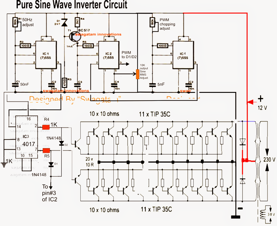
The first circuit is the basic sine wave generator which becomes the feeding input to the main sine wave amplifier or the output stage.
It comprises a cd4047 multivibrator (ic1), irf250 mosfets (t1 through t8), transistors and a few discrete components.
Few days ago, gohz made a 24v 2000w power inverter in home, sharing some design schematics and circuit diagrams. 600w pure sine wave power inverter spwm driver board Pure sine wave inverter using arduino. 500w, amplifier, circuit, subwoofer.a 500w amplifier will work with a 500va to 1000va in all domestic duty.hi all, new to this forum, i am currently trying to repair an old 500w stageline amplifier, i am relatively new to electronics and circuitry and any help and guidance would be realy appreciated, i do have a schematic for this and have already replaced.
My second question is can i replace 2uf with 2n2 400v ( 2.2nf,) or can use 2.2/50v electrolytic cos 2uf cannot be found here i therefore cherish the hope that my question will meet
Simplest inverter using hybrid mosfets and igbts with unipolar pwm to scientific diagram. Part of the h bridge circuit uses a conventional circuit. First with a double voltage module voltage for the op amp power supply. To actually implement the design of this 500 watt pwm dc/ac 220v power inverter, certain steps had to be taken to ensure that every unit of the project functions correctly.
Many drawbacks and flaws were detected while assessing the above circuit details.
Can anyone please give me the 500w pure sine wave inverter circuit diagram and its component details and its explanation? 500w pure sine wave inverter dc 12v to ac 240v/220v/110v/230v, 50/60hz output frequency, 12 volt 500 watt pure sine inverter provides the safest option for circuit board power supply. High efficiency 24v 500w pure sine wave inverter for home use, dc 24v to ac 230v, 240v, 220v, 110v, 100v are available, output frequency can choose 50hz or 60hz. Because this part of the circuit is relatively simple, so i did not draw schematics, pcb diagram is drawn directly.
Pure sine wave inverter implementation and circuit diagram
Output short circuit, the machine shut down output, buzzer and lights at the same time work. By debashis das aug 28, 2020 4. The above circuit may be further enhanced with an automatic load correction feature. 24v pure sine wave inverter is widely used in microwave oven, tv and air conditioner.
Microtek inverter circuit diagram pdf electrical learner.
Please i need 6000 watt sine wave inverter 220 v ac. I want to make pure sine wave inverter. 500w car power inverter, bmk car converter pure sine wave dc 12v to 110v ac car plug inverter adapater with 1 type c port 2 usb ports 2 ac outlets. Mar 13, 2011 #2 t.
Inverter circuits are often needed where it is not possible to get ac supply from the grid.
The finalized circuit (hopefully) is presented below. This project is a stepping stone to a cheaper and efficient pure sine. Get it as soon as mon, mar 28. 4.4 out of 5 stars.
Sine wave inverter circuit description.
Projects 500w 12v to 220v eleccircuit com 2000w power with diagrams gohz 12 volt 1000 design process tbe t12p1000w pure sine wave w usb input lazada ph service manual rar schematic diagram preview 500 battery charger 12vdc 220vac sch eeprom repair info for. Op amp 1 generates a 50 hz sine wave as the reference signal. Op amp 2 as an inverter. Here are 600 watt power inverter pcb shots of the power board, length and width is 200x150mm.
The couple of designs shown below are all that would be required for implementing this simple pure sine wave inverter circuit.
Ups inverter diagrams pdf free 3000w power 12v to 230v digital circuit diagram 4 simple uninterruptible supply sinewave using pic16f72 homemade solar m 100 watt offline engineering projects electronic abc home facebook sine wave build 200w 500 with battery circuits 2000w homage schematic microtek how an works. The icl7660 or max1044 can be selected. An inverter circuit is used to convert dc power to ac power and it can be divided into two types that is pure sine wave inverters or modified square wave inverters. With irf1404 as the mosfets, the inverter would be able to generate anywher around 300 to 5000 watts of pure sine wave output.
I have got pure sine wave in my final year project ” hybrid pure sine wave inverter ” after connecting a lc filter at the output of h bridge.i have lc values l= 2mh and c= 3.3uf.diagram of pure sine i have got in my final year project is shown in figure below: