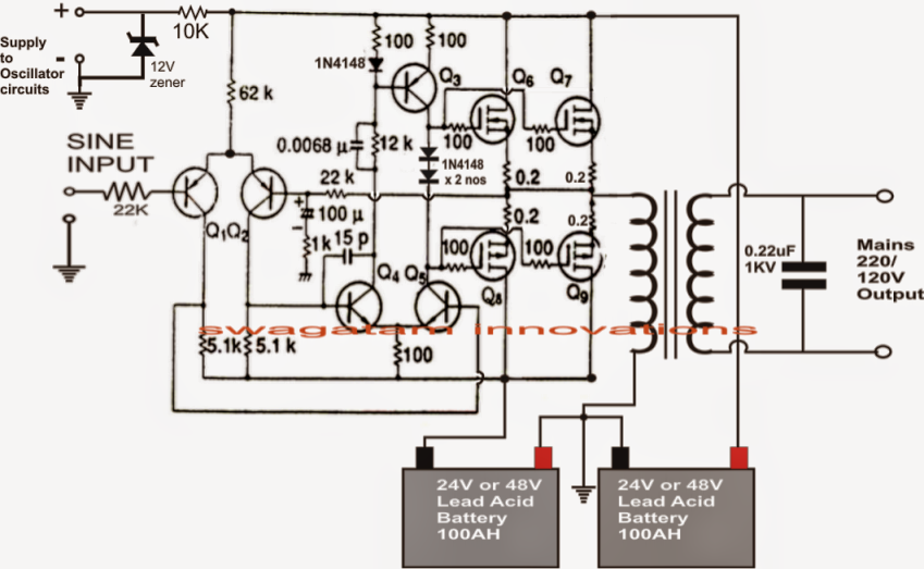
There would be a period of time when neither mosfet was switched on. The frequency can be from 50 to 60 hz; Posted tuesday, april 30, 2013.
Inverter und Oszillator
N1, is wired as an oscillator circuit, for generating the required 50 or 60hz pulses.
Because of using 555 timer and mosfet as main.
This circuit can be used as the front end of circuits that require precision 50hz pulses. This is due to the tolerance of the capacitors and resistors which creates inaccuracy. It produces alternating 50hz pulses with 50 per cent duty cycle, which can be used in inverter circuits. This ic is used to generate the 50hz frequency required to generate ac supply by the inverter.
We use the cmos chip cd4069b inverter gate.
We will try to take an inverter gate or not gate to test the fun circuit. A 4.9152 mhz crystal is used in the circuit to generate. Hopefully the pictures above wiring diagram can be useful. It takes time for the output level to reach maximum because the oscillator gain is turned down instead of using an amplitude stabilizing circuit.
I experiment it to work well.
Here is an ic 555 inverter circuit. Download scientific diagram | output sine wave (50 hz) of the wien bridge oscillator from publication: This is to make the waveform nearer to a sine wave. How to make a 50 hz oscillator for the inverter.
These are appropriately inverted and buffered using the remaining gates n2, n3, n4 in order to finally deliver the alternately switching frequency across the bases of the power bjts, which in turn switch the power transformer at the supplied rate for generating the required 220v or.
Cd4060 is the ripple free binary counter ic and its basic frequency is controlled by a crystal connected in its pin 10 and 11. The 2n3055 piece and 5watts 220 or 330 register 2 pieces. Nevertheless, this need to be a centre tapped winding. Even this does not work with some equipment such as induction motors.
Sinusoidal pwm signal generation technique for.
An inverter is different because it is efficient. Automatic ups system wiring circuit diagram for home or office new design with one live wire wiring and installation. And using a few parts and a small circuit. Although they work in simulation, their component values may need altering or additional components may be necessary when the circuits are built.
If the gain is higher or lower than the optimum value, the wien bridge often fails to work properly.
Unit will cut out and must be manually restarted: My circuit designs should be regarded as experimental. You can change the resistor r2 in values from 5 kom to 50 kom for fine tuning of the frequency.kako napr. When use source is 12v battery will have the output of 220v ac 50hz.
60 to 50 hz · 50 to 60 hz · 60 to 60 hz isolation · 50/60 to 400 hz.
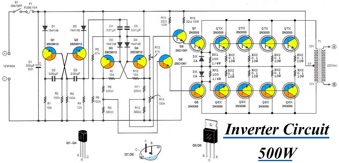
The circuit uses two counter ics cd4060 and cd 4017 to divide the basic frequency to generate 50 hz pulses. The circuit consists of astable multivibrator which uses two transistors and tuned to generate 50 hz to 60 hz at 50% duty cycle. Do you want to learn a simple inverter circuit? We have so many collections wire wiring diagrams and schematics, possibly including what is you need, such as a discussion of the inverter circuit diagram 1000w pdf.
The output is about 50 watts.
A cmos inverter works extremely well in the popular hartley type oscillator, and this has the advantage within the earlier design that just a single winding is required within the coil. Let’s experiment uses not gate as an oscillator circuit. The circuit diagram of a cmos hartley oscillator is shown in below diagram. Modern inverters step up the input voltage first using a high frequency inverter to about plus and minus 300 volts dc then do the 50 hz switching.
This astable multivibrator acts as oscillator for this inverter.