2000w inverter circuit diagram this is the circuit diagram of 2000w high power inverter circuit. None of those schemes is good; Assume an operating mode 2.
Interfacing Microcontrollers to CMOS and MOSFET Circuits
This is based on the mosfet3205.
Download a better high resolution circuit diagram here.
Now you know how a basic inverter works. Experiment with overlocking and underclocking a cmos circuit; 4 years, 6 months ago. The inverters can be applied directly to the design of logic gates and other more complex digital circuits.
An understanding of mosfet switching circuits.
The arrangement of the inverter consists of four transistor, (mosfet or igbt).to obtain an ac waveform at the output, the transistors are turned on and off in pairs of q 1, q 2 and q 3, q 4. This is another 100 watt inverter circuit diagram. More experience with the elvis ii, labview and the oscilloscope; This is the inverter 100w circuit, use ic 4047 alike inverter 100w transistor i use mosfet irf540 instead transistor 2n3055.
Enforce the equality conditions of that mode.
4) after that, solder the irfz44n mosfets on the pcb board. This one is simpler and more efficient in terms of inverting, however the mosfet only lets a small voltage and current through, hence 9v are required for a single led. Basic mosfet logic gates 3.1 inverter when building digital gates out of mosfets, we will be observing three basic rules: Inverter circuit is one of the fundamental building blocks in digital circuit design (not to be confused with a power inverter).
Equivalent circuit of the mosfet based half‐bridge dc‐ac.
Check the inequality conditions of the mode for consistency with original assumption. 4 years, 6 months ago In a previous circuit, which you can find on my profile, i showed how to make an inverter with an npn transistor. + all static parameters of cmos inverters are superior to those of nmos inverters + cmos is the most widely used digital circuit technology in.
2) after that, solder the 2sc1815 transistors on the pcb board.
6) connect the 12v dc power jack with. 5) solder the input and output terminal block connectors on the pcb board. Let's learn more about the circuit functioning. Analyze the circuit with the enforced conditions.
Irf540 n vishay siliconix power mosfet is used for this inverter circuit as switching drivers.
Continue to develop professional lab skills and written communication skills. Although it is possible to reduce the circuit of figure 4.3(b) to that of figure 3.2(b), it is generally difficult to do so. • complementary mos (cmos) inverter analysis makes use of both nmos and pmos transistors in the same logic gate. Click on image for best resolution click to.
Sources, we must follow these five steps:
The lm324 is simply too slow to drive a mosfet gate in any inverter operating at a reasonable speed. 1 shows single phase bridge inverter with resistive load. Make an inverter parts required. Which themselves require inverters to generate from the original input signals.
Bc548 / any npn transistor x 2;
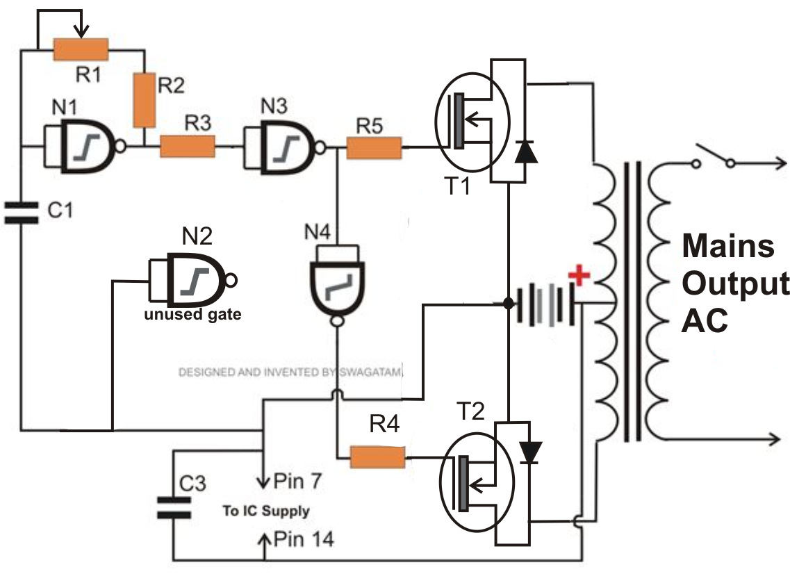
In order to make this homemade inverter 12v to 220v we will need the following parts: Read detail more in circuit. N1, n2, n3, n4 not gates from the ic 4049 are arranged as a voltage doubler circuit, which generates about 20 volts from the available 12v supply. Bootstrap power supply‐circuit for a half‐bridge inverter.
Thus to obtain a positive voltage (+v) across the load, the transistors q 1 and q 2 are turned.
Mosfet circuits to analyze mosfet circuit with d.c. The transfer characteristics of an ideal inverter is shown below. Please careful with this circuit because high a voltage. Electronics 2021, 10, 390 4 of 17 load ir2112 figure 3.
It provides fast switching and a high operating temperature (175ºc).
Simple 12v to 230vac inverter circuit. An electrical transformer no center tap (from old radio, car charger) and a dc power supply (battery,battery pack from 18650,car auto battery) R => r4+vr2, c=> c3, please see the following. 1) first of all, solder all the resistors on the pcb board.
Mosfet is a low cost.
In the circuit diagram we can observe that 12v battery is. Use 24v dc supply for operation and connect 24v 5a or more than 5a transformer. 3) solder the 10uf capacitors on the pcb board. 100 watt inverter 12vdc to 220vac with mosfet.