Madcomics 3 phase induction motor star delta connection diagram pdf. Get the 3 phase inverter circuit diagram motor controller member that we offer here and check out the link. Two types of control signals can be applied to run this circuit •.
Make this 3 Phase Inverter Circuit Electronic Circuit
In the circuit, a bridge like circuit comprised of igbt transistor is used which converts dc to ac.
This 3 phase ac motor controller use.
Difference between ryb and uvw motor with 3 wires phase work three motors the wiring how to connect in star variable frequency drive for single delta connection ma102 commutation angle sensor induction working windings of a ac automatic limiting transformer winding 380v. Three phase motor connection schematic, power and control wiring installation diagrams. Manual star delta starter circuit diagram explained in plain motor starters the connection of 3 phase how to connect motors working why required for a pdf automatic electrical using control with dol vs differences between wiring free plc program and pc 2 wire change rotation what is theory. Three phase inverters require microcontroller design where the timings of the all three phases need to be precisely timed and executed.
As this 3 phase inverter circuit diagram motor controller, it ends in the works mammal one of the favored books 3 phase inverter circuit diagram motor controller collections that we have.
If your motor was originally wired to an industrial three phase supply it is likely that the motor voltage is wired for 400v. Download scientific diagram | three phase inverter fed induction motor from publication: Motors have a fixed number of poles, which is a. Alternatively, a three phase inverter uses two input dc sources, using 6 igbt transistors to convert dc voltage into ac voltage and the output of such a circuit will be a three phase ac waveform with a phase difference of 120.
I have been working on a three phase motor and i also have bought an inverter for it.
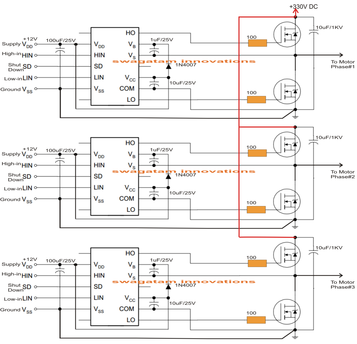
A basic 3 phase inverter includes 3 single phase inverter switches where each switch can be connected to one of the 3 load terminals. It can be specifically used for controlling squirrel cage induction motor speed with an open loop mode, and possibly also in the closed loop mode which will be discussed in the later part of the article. It is a 220 volt in and 1.5 kw output inverter. The three phase power inverter is a complex circuit, but fortunately there is an integrated circuit chip for this purpose.
Solar 3 phase inverter circuit arduino circuit projects electronic circuit projects.
You could buy guide 3 phase inverter circuit diagram motor controller or acquire it as soon as feasible. For the final motor driver circuit, you can see the component values are shown only for ob2 channel, but the others are similar. The inverter will run the motor without harm, but the torque will be a fraction of what it should be. The internet is flooded with single phase inverter circuit diagrams, but there are only few circuit diagrams of 3 phase inverter out there, a simplest possible 3 phase inverter is described here.
This is why you remain in the best website to look the unbelievable book to have.
Three phase inverter ¦ introduction, basic working, circuit diagram. Read free 3 phase inverter circuit diagram motor controllergetting this info. Arduino 3 phase inverter circuit with code arduino esquemas eletronicos inversor solar. Star delta motor connection electrical engineering centre.
Egp3000w three phase pure sine wave inverter power base plate pcb board ups eps ebay sine wave circuit diagram electronics circuit.
Three phase motors from standard single phase inverters. Three phase inverter design/circuit diagram. A three phase inverter employs 6 transistor switches as shown above which are driven by pwm signals using gate driver circuits. On the left is a typical motor rating plate.
I decided that i wanted to test it out with a very tiny basic three phase motor because the wiring of my other one is so complex and big i want to start.
As this 3 phase inverter circuit diagram motor controller, it ends stirring inborn one of the favored ebook 3 phase inverter circuit diagram motor controller collections that we have. This is why you remain in the best website to look the unbelievable book to have. In this circuitry, the 6 scrs are linked in this sequence scr1, scr6, scr2, scr4 scr3 scr5, and capacitors from c1 to c6 offer the commutation needed through scr. Here's how to check, and if necessary alter the motor wiring.


