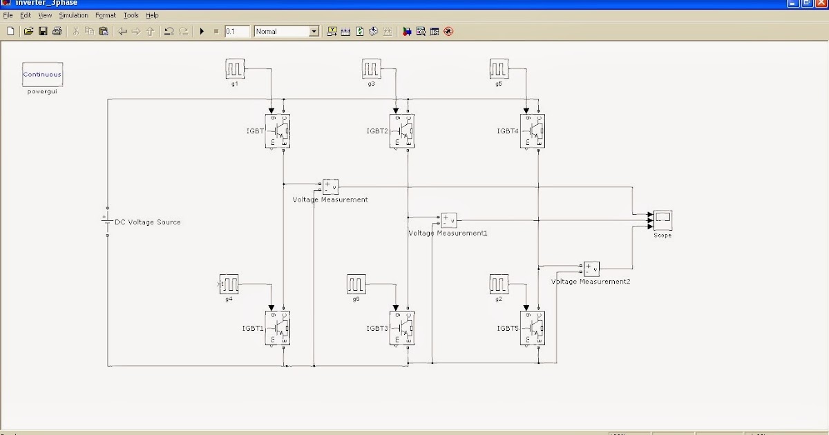
Three phase inverters require microcontroller design where the timings of the all three phases need to be precisely timed and executed. Simplest inverter using hybrid mosfets and igbts with unipolar pwm to scientific diagram. In the explanation below, we will design a three phase inverter in simulink.
MOSFET selection for BLDC motor drive Electrical
Three phase inverter design/circuit diagram.
These spwm signal are 120 degree out of phase with each other.
A basic 3 phase inverter includes 3 single phase inverter switches where each switch can be connected to one of the 3 load terminals. The internet is flooded with single phase inverter circuit diagrams, but there are only few circuit diagrams of 3 phase inverter out there, a simplest possible 3 phase inverter is described here. Now you know how a basic inverter works. The pwm of phase a, b, and c is usually jointly controlled by a triangular wave carrier v.
Arduino is used to generate spwm singals to drive gate driver circuits as shown in figure below.
When the load is purely resistive, a six step waveform is obtained (fig. We will have a brief look at the three phase transformer working and we will construct a three phase transformer using three “single phase transformer” by combining the windings in delta and start connections. In this article, we will discuss 3 phase inverter circuit which is used. In the graph, we can see three voltage waveforms are out of phase with each other by 120º.
3 phase inverter with capacitive filter.
It can be used to drive a bldc motor. Three phase inverter circuit diagram. If we draw the voltage waveforms for each phase then we will have a graph as shown in the figure. Some of the harmonics are suppressed and a smoother waveform is obtained.
The circuit below shows a 3 phase inverter inverter circuit stage using h bridge mosfets configuration which receives the phase shifted pwms from the above stage and converts them into corresponding high voltage ac outputs for operating the connected 3 phase load normally this would be a 3 phase motor.
Download a better high resolution circuit diagram here. Three phase inverter a three phase inverter employs 6 transistor switches as shown above which are driven by pwm signals using gate driver circuits. Simple 12v to 230vac inverter circuit. A first order capacitive filter is used.
It is usually controlled in a bipolar manner.
The fourth one is having current rating of 450ma. In this post we learn how to make a simple microprocessor arduino based 3 phase inverter circuit which could be upgraded as per user preference for operating a given 3 phase load. All three bridge should be operate such that all of them should be 120 degree out of phase with each other. An arduino three phase inverter is a circuit which produces a 3 phase ac output through a programmed arduino based oscillator.
The designed system generates 223v square signals at each phase from a 12v battery through switching of three stages of power mosfets using pulse width modulation (pwm) signals at their gates from an arduino uno.
3 phase inverter with resistive load without using any filter. We have already studied an effective yet simple. Full pdf package download full pdf package. 37 full pdfs related to this paper.
Bc548 / any npn transistor x 2;
Alternatively, a three phase inverter uses two input dc sources, using 6 igbt transistors to convert dc voltage into ac voltage and the output of such a circuit will be a three phase ac waveform with a phase difference of 120. A short summary of this paper.