It is used in many industrial as well as domestic applications. Following is a schematic for a three‐phase inverter with a 3‐phase, wye connected, resistive load attached: We have already studied an effective yet simple.
81 3 PHASE INVERTER CIRCUIT DIAGRAM USING IGBT
I am in search of finding a 3 phase inverter circuit.which converts a dc supply of 12v to 3 phase output waveforms found more circuits of transistor pairs 3 in parallel.
In this post we learn how to make a simple microprocessor arduino based 3 phase inverter circuit which could be upgraded as per user preference for operating a given 3 phase load.
An arduino three phase inverter is a circuit which produces a 3 phase ac output through a programmed arduino based oscillator. A single phase inverter takes the dc voltage as input and converts it to single phase ac voltage while a three phase inverter converter converts the dc voltage into three phase ac voltage. Three phase inverter is used in. Three phase sine wave inverter is used in many applications.
What is three phase inverter?
In this project, three phase sine wave inverter is designed using atmega2560 microcontroller. Online library 3 phase inverter circuit diagram motor controller 3 phase inverter circuit diagram motor controller right here, we have countless books 3 phase inverter circuit diagram motor controller and collections to check out. A galvanically isolated system was installed between the pv array and the ac grid. Three phase sine wave inverter is more often used in power electronics application where power requirement is greater than 10kva.
But there are no connection to base of transistors.plzzz any one help for connection of.
This can be achieved using inverters. Based on the type of supply, there are two types of inverters: We additionally meet the expense of variant types and as a consequence type of the books to browse. Three phase inverters can be realized in two ways:
Pure sine wave inverters generate supply consisting of a single sinusoid.
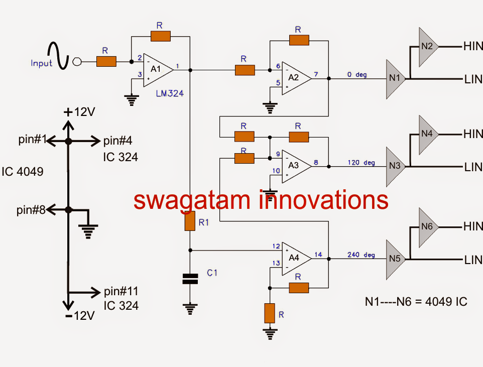
3 phase inverter circuit using igbt author: This project presents the design of a 3 phase inverter to drive bldc motors and other general purpose 3 phase loads and its simulation in ngspice ii. Download scientific diagram | 1, three phase inverter circuit from publication: The three phases are available at pins 9, 10 and 11.
According to whether the carrier wave and the modulation signal are synchronized has asynchronous and synchronous modulation two.
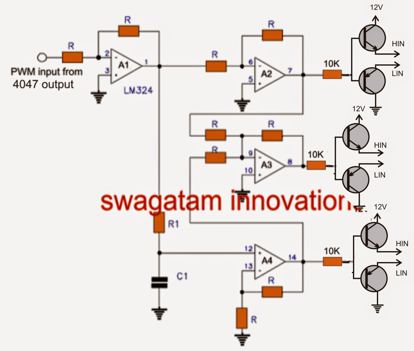
The pwm of phase a, b, and c is usually jointly controlled by a triangular wave carrier v. 3 phase inverter circuit using igbt keywords This document describes inverter circuits used for motor control and other applications, focusing on pwm control. The circuit consists of an arduino which generates the 3 phase waveform with 120degree electrical phase difference between each individual waveform.
If no current flows into the parasitic capacitance capacitors, the grid current is in a smooth sinusoidal curve.
They are durable and sustainable to offer consistent service relentlessly without the chances. Here, step is defined as a switching sequence of scr or firing from one scr to the next scr in a sequence. It is usually controlled in a bipolar manner. Program codefor 3 phase inverter circuit:
Classes of inverters inverters are classified as pure sine wave and modified sine wave inverters.
You can select from the existing 3 phase inverter circuit models on the site or go for completely customized versions of these products. Alternatively, a three phase inverter uses two input dc sources, using 6 igbt transistors to convert dc voltage into ac voltage and the output of such a circuit will be a three phase ac waveform with a phase difference of 120. A three phase inverter employs 6. Three single‐phase inverters operating together, or one three‐phase inverter.
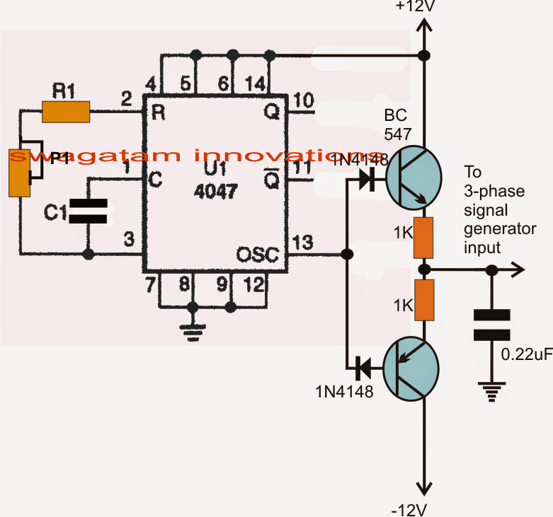
The circuit concept the oscillator and the pwm stage.
Single phase inverter and three phase inverter. The ic 4047 is wired as a standard flip flop output generator at the rate of the. In the explanation below, we will design a three phase inverter in simulink. In the above 3 phase generator circuit (second last diagram) using a sine wave.