Introduction an inverter is basically a converter. •compact design for low total module resistance. Single phase inverter and three phase inverter.
84 3 PHASE INVERTER CIRCUIT DIAGRAM USING MOSFET
The digital logic blocks controlling the multisim design are developed in labview.
The circuit work fine for low watts motors but not for high power motor(1kw).
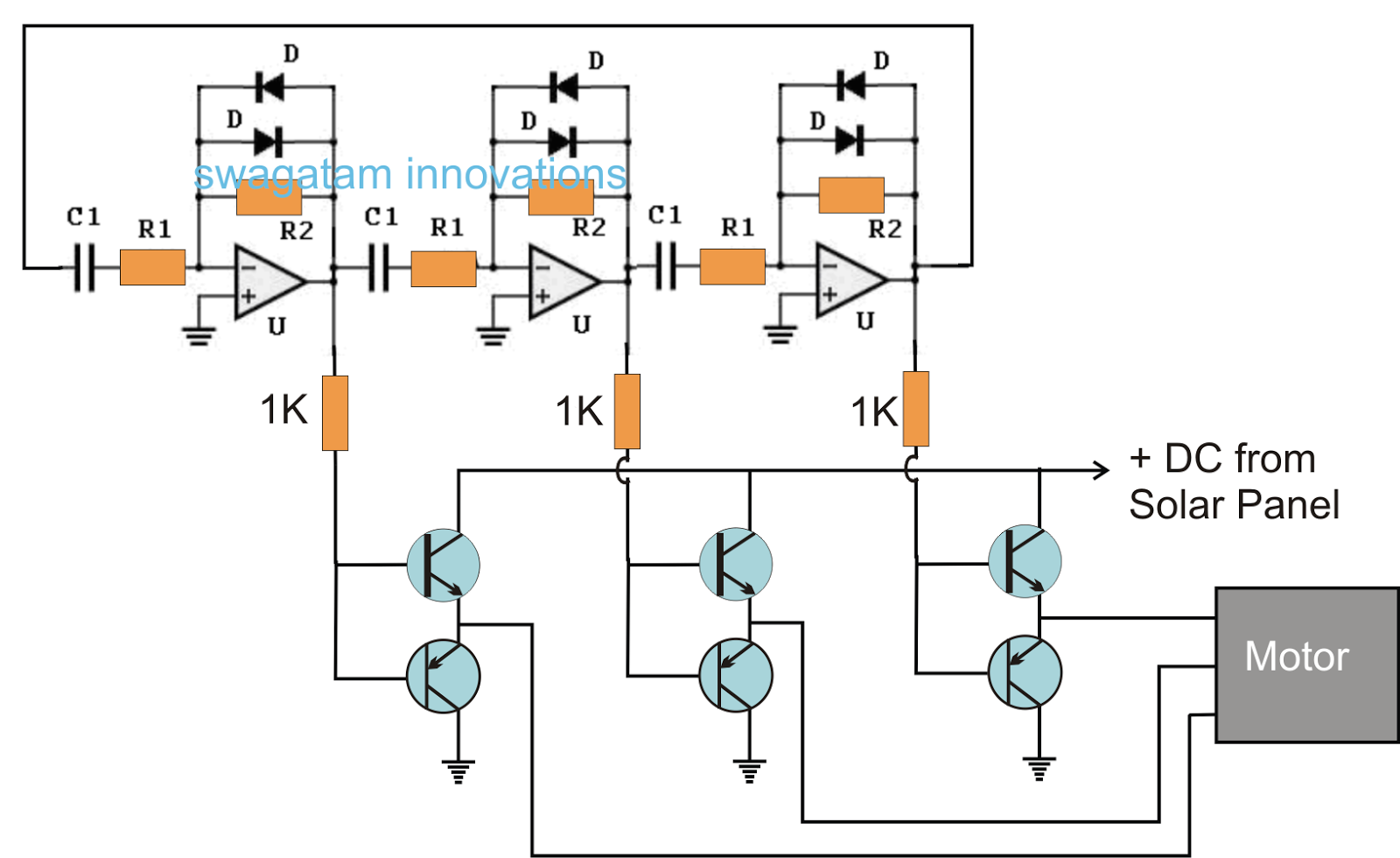
The mosfets swiches good, but when i connected to 1kw motor (at 20v and 10amp supply) the mosfet gets heated up above 60c. These spwm signal are 120 degree out of phase with each other. I want to design 3 phase inverter that will be connected to the grid (380vac) using mosfet , what is the minimum rating voltage on the drain of the mosfet transistor? We have already studied an effective yet simple 3 phase inverter circuit in one of our earlier posts which relied on opamps for generating the 3 phase square wave signals, while the 3 phase push pull signals for driving the mosfets was implemented using specialized 3 phase driver ics.
The output signal from the mosfet is 180 degree inverted (again) from the bjt’s output, now we got zero degree phase shift with respect to arduino’s output.
I used atmel328p processor, gate driver and 12 mosfets. Nov 27, 2016 nov 27, 2016 Arduino is used to generate spwm singals to drive gate driver circuits as shown in figure below. A three phase inverter employs 6.
Design and simulation of single phase, three phase and pulse width modulated inverter and use of pulse width modulated inverter in the speed control of induction motor.
Alternatively, a three phase inverter uses two input dc sources, using 6 igbt transistors to convert dc voltage into ac voltage and the output of such a circuit will be a three phase ac waveform with a phase difference of 120. In the graph, we can see three voltage waveforms are out of phase with each other by 120º. Phase from a 12v battery. Each gate drive will control one mosfet.
•electrically isolated dbc substrate for low thermal resistance.
The gating signals of single phase inverters should be delayed by 120° with respect to each other to obtain three phase balanced voltages. Its stator leakage inductance l. Could anyone please tell me what is wrong in the simulation to get the output properly. I am trying to build a 1kw bldc inverter circuit.
The designed system generates 223v square signals at each
Inverters can be with any specifications, but a standard inverter has these important stages: •rc snubber for low emi. Here the mosfets‟s are controlled by gate drive; •three−phase inverter bridge for variable speed motor drive.
The output at the mosfet is now a strong which can drive the three phase transformer.
I have designed three phase inverter in ltspice with spwm technique using mosfet switch. •current sensing and temperature sensing. The output voltage at the load is incorrect. A single phase inverter takes the dc voltage as input and converts it to single phase ac voltage while a three phase inverter converter converts the dc voltage into three phase ac voltage.
The inverter is modeled using the universal bridge block and the motor by the asynchronous machine block.
The circuit consists of an arduino which generates the 3 phase waveform with 120degree electrical phase difference. Inverter, mosfet, relays, transformer, diode, ic. The designed system generates 223v square signals at each. If we draw the voltage waveforms for each phase then we will have a graph as shown in the figure.
Power inverters can deliver power anywhere between 10 watts to 10000 watts depending on your needs and inverters can also be single phase or three phase depending on your application.
Three phase inverter is formed by three single phase inverters which are connected in parallel; In the explanation below, we will design a three phase inverter in simulink. In the present concept also we configure the main power stage using these. Based on the type of supply, there are two types of inverters:
All three bridge should be operate such that all of them should be 120 degree out of phase with each other.
Three phase sine wave inverter is designed using arduino microcontroller. Three phase inverter automotive power mosfet module nxv08v110db1.