Three phase inverter output controlled by the phase ac supply. S3, s6 and s5, s2 are turned on with a time interval of 180°. Each gate drive will control one mosfet.
THREE PHASE VOLTAGE SOURCE INVERTER Altair University
The switches used in the inverter have 50% of ratio and switching can be occurred after every 60 degrees angle.
Grid source is three of inverters.
The inverter is build of switching devices, thus the way in which the switching. Thyristors 1 & 6 conduct 0 v an = , , v cn = 0 Switch in the upper group i.e. It means that s1 conduct for 180° and s4 for the next 180° of a cycle.
New ic, ir2233, reduces gate drive component counts by 88%, pcb space by 66% and production cost by.
Generally, the three arms of this inverter will be delayed with 120 degrees angle to generate a 3 phase ac supply. Three phase inverters can be operated in to two different types of modes of conduction, i.e. This equipment should be connected to inverters with a rated power If we draw the voltage waveforms for each phase then we will have a graph as shown in the figure.
Current sensing circuit design guidelines an4076 4/14 doc id 022923 rev 1 1 current sensing circuit design guidelines figure 2 shows, in more detail, the block diagram of the power stage where two (or three) shunt resistors are placed on the bottom of two (or three) inverter legs.
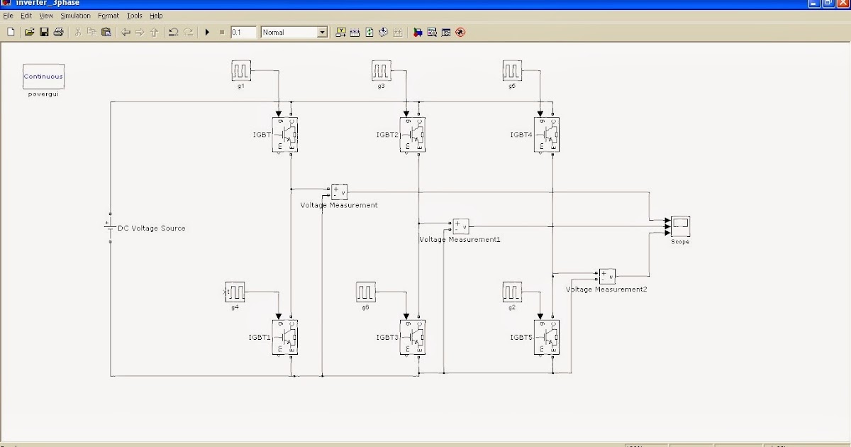
In each case, the effective resistance across the source is 2r as shown 15.5. Take a screenshot of all three phases of output voltage on the scope. In the following three phase inverter circuit process the three single phase inverters put across the same dc source. In the three phase inverter of each switch conduct 180° of cycle, thyristor pair in each arm i.e.
Here the mosfets‟s are controlled by gate drive;
The gating signals of single phase inverters should be delayed by 120° with respect to each other to obtain three phase balanced voltages. The gate drive circuit comprises of three ucc21520 devices, which are dual igbt gate drivers. Three phase inverter is formed by three single phase inverters which are connected in parallel; Read free 3 phase inverter circuit diagram motor controller3 phase inverter circuit diagram motor controller recognizing the pretension ways to get this book 3 phase inverter circuit diagram motor controller is additionally useful.
This is why you remain in the best website to look the unbelievable book to have.
In the circuit, a bridge like circuit comprised of igbt transistor is used which converts dc to ac. You may use your favorite arduino board. As this 3 phase inverter circuit diagram motor controller, it ends in the works mammal one of the favored books 3 phase inverter circuit diagram motor controller collections that we have. Use a 20 v dc source as input.
What’s the rms voltage of each phase?
In the graph, we can see three voltage waveforms are out of phase with each other by 120º. This equipment is not intended for use in residential environments and may not provide adequate protection to radio reception in such environments. A power stage module and a control module. The ucc21520 has many features to design a reliable three phase inverter.
The pole voltages in a three phase inverter are equal to the pole voltages in single phase half bridge inverter.
The circuit consists of an arduino which generates the 3 phase waveform with 120degree electrical phase difference between each individual waveform. Variable frequency drive (vfd) is an essential. This board performs the function of dc/ac conversion. Hook up and run a 3‐phase, 1800modulation inverter.
The switches like s1, s2, s3, s4, s5, and s6 will complement each other.
It having amplitudes (va=230, vb=230 sine pulse width modulated (spwm) pulses generated by and vc=230), frequencies (fa=fb=fc=50hz) and phases the. Alternatively, a three phase inverter uses two input dc sources, using 6 igbt transistors to convert dc voltage into ac voltage and the output of such a circuit will be a three phase ac waveform with a phase difference of 120. In this article, we will discuss 3 phase inverter circuit which is. For these three modes of operation:
Connect a 200 ω/phase, wye‐connected load to the inverter.