The igbt are triggered accordingly such that the ac output voltage is obtained at the output. Rg (on) = 25 ohm. We will have a brief look at the three phase transformer working and we will construct a three phase transformer using three “single phase transformer” by combining the windings
Simple 3 Phase Inverter Circuit Circuito, Electricidad y
12 3 phase igbt inverter circuit diagram.
Download free 3 phase inverter circuit using igbt 3 phase inverter circuit using igbt | ebd815f6895bcab7088eab86ce4e629a hybrid electric vehicle system modeling and controlmodeling for hybrid and electric vehicles using simscapescientific and technical aerospace reportsplant and process engineering
Based on the type of supply, there are two types of inverters: Q3 and q4 are simultaneously turned on to form a freewheeling circuit, so the waveform of the output voltage. Read free 3 phase inverter circuit diagram motor controllerseries 1.0. Single phase inverter and three phase inverter.
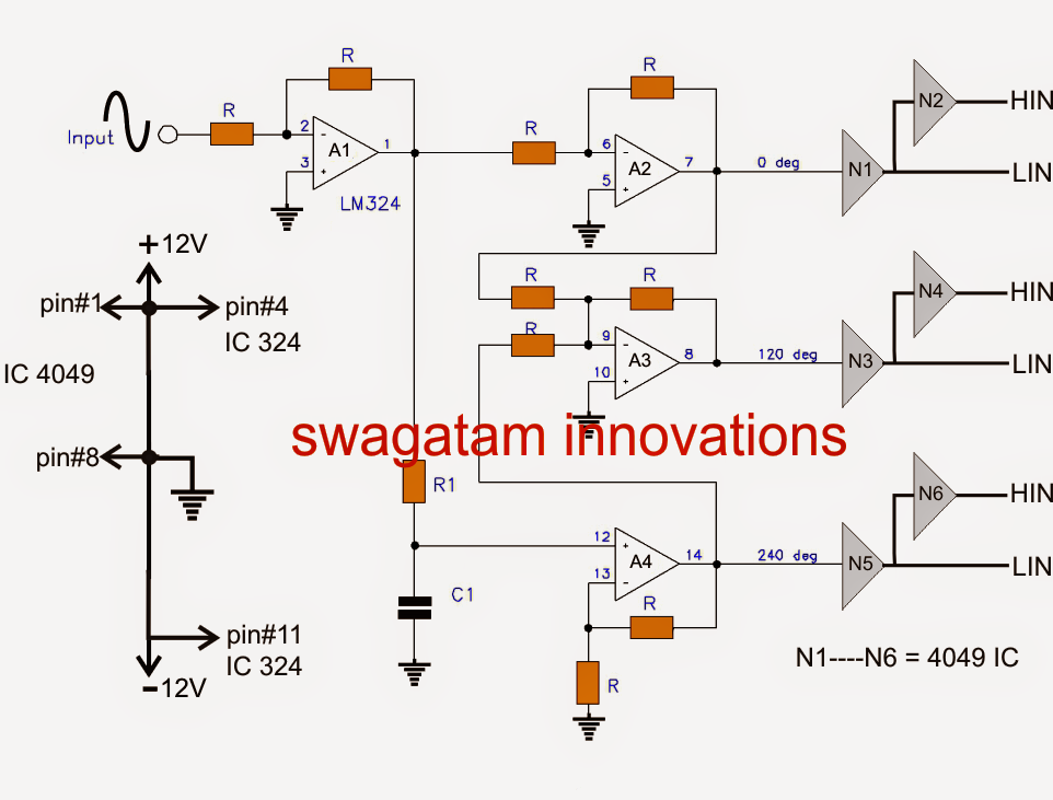
Alternatively, a three phase inverter uses two input dc sources, using 6 igbt transistors to convert dc voltage into ac voltage and the output of such a circuit will be a three phase ac waveform with a phase difference of 120.
Harmonic reduction in the parallel arrangements of grid. Design three phase inverter using simulink matlab Igbt based three phase inverter kit; My design is as under.
While it is a better tester is […]
Vg (off) =0v for high side and also for low side. Design of three phase inverter using igbt. Vg (on) =15v for high side and also for low side. A three phase inverter employs 6.
This board performs the function of dc/ac conversion.
Bootstrap capacitor value is = 1uf/25v. It comprises of two boards: Read free 3 phase inverter circuit diagram motor controller3 phase inverter circuit diagram motor controller recognizing the pretension ways to get. In the graph, we can see three voltage waveforms are out of phase with each other by 120º.
Switching frequency is = 4khz.
Rg (off) = 5.6 ohm. Read online 3 phase inverter circuit using igbt 3 phase inverter circuit using igbt | ebd815f6895bcab7088eab86ce4e629a bsnl jr. 1a fuse and 6a fuse; In this article, we will discuss 3 phase inverter circuit which is.
The phase between q1 and q2 is 180° out of phase, and the value of the output ac voltage varies with the output of q1 and q2.
The circuit diagram consists of four distinct igbt such that they are connected as the bridge circuit. Igbt is a mosfet and gtr composite device, so it has work fast, big input impedance, simple driving circuit, simple control circuit, higher operating frequency, large element capacity. The operation of the circuit is as follows. In the explanation below, we will design a three phase inverter in simulink.
Engineer (tta) exam guide + practice.
This document describes inverter circuits used for motor control and other applications, focusing on pwm control. I am using three half bridge igbt modules specified as above in three phase inverter. First the igbt s1 and s4 are turned on by. In the explanation below, we will design a three phase inverter in simulink.
The input to the circuit is the 220v dc supply from the rectifier unit.
Circuit diagram of an igbt. A practical guide to free energy devices motionless pulsed systems chapter 3 ultimate energizer in 2020 free energy projects free energy zero point energy in principle a drive. A power stage module and a control module. A single phase inverter takes the dc voltage as input and converts it to single phase ac voltage while a three phase inverter converter converts the dc voltage into three phase ac voltage.