In this website so far we have mostly discussed and incorporated the irs2330 (or 6edl04i06nt) for implementing a given 3 phase driver application such as a 3 phase inverter or a bldc motor controller, and assumed this to be the easiest option using ordinary discrete components. Sine wave inverter circuit description. This document describes inverter circuits used for motor control and other applications, focusing on pwm control.
(PDF) Grid Connected Three Phase Inverter
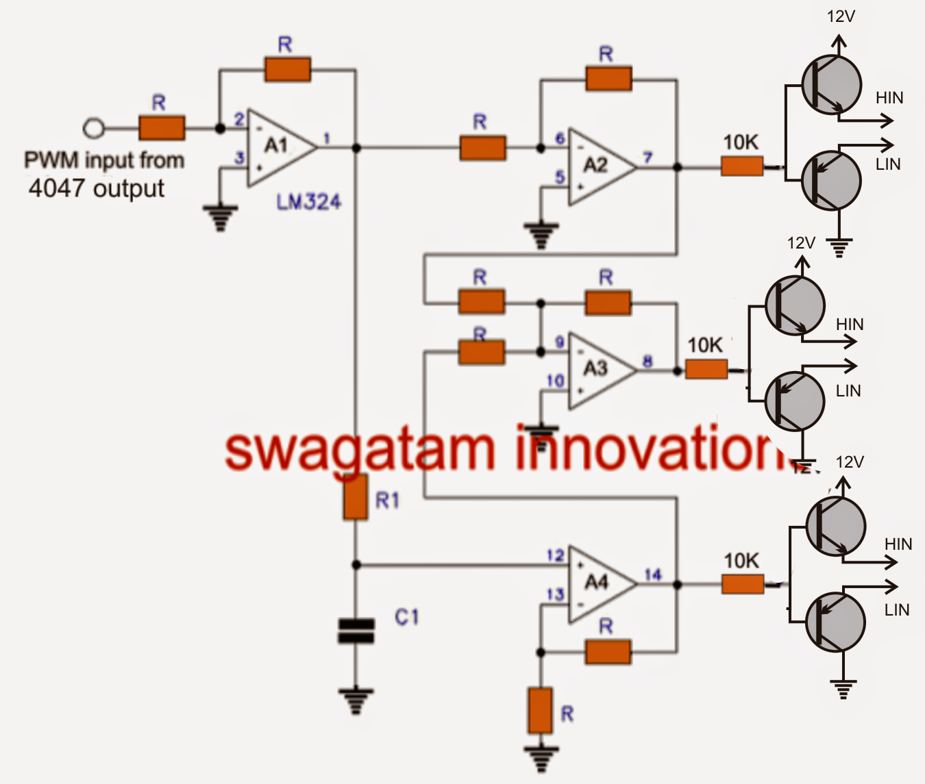
A three phase inverter employs 6 transistor switches as shown above which are driven by pwm signals using gate driver circuits.
Each part ought to be placed and connected with other parts in…
Three phase inverter circuit diagram diy electronics projects power of an igbt based single full bridge scientific simple 3 homemade 120 degree and 180 conduction mode 12v dc to 220v ac pcb make your own sine wave explanation pdf design implementation a specific grid tie for agent microgrid smps welding easy sg3525 circuits explored overcur short. A basic 3 phase inverter includes 3 single phase inverter switches where each. Download file pdf 3 phase vfd schematic circuit diagram 3 phase vfd schematic circuit diagram getting the books 3 phase vfd schematic circuit diagram now is not type of inspiring means. Igbt is a mosfet and gtr composite device, so it has work fast, big input impedance, simple driving circuit, simple control circuit, higher operating frequency, large element capacity.
Read online igbt inverter circuit diagram not known to modern engineers.
A power stage module and a control module. It comprises of two boards: The inverter is an electrical switching control device that can be converted from one source to another source like as dc to ac or ac to dc. This board performs the function of dc/ac conversion.
Alternatively, a three phase inverter uses two input dc sources, using 6 igbt transistors to convert dc voltage into ac voltage and the output of such a circuit will be a three phase ac waveform with a phase difference of 120.
1 shows the sine wave inverter circuit of the While it is a better tester is […] The achievable power rating of the inverter is governed not just by the igbt devices but also by the coupling of the gate drive circuit. Two types of control signals can be applied to run this circuit •.
A practical guide to free energy devices motionless pulsed systems chapter 3 ultimate energizer in 2020 free energy projects free energy zero point energy in principle a drive.
Circuit diagram of an igbt. 12 3 phase igbt inverter circuit diagram. Three phase inverter circuit diagram diy electronics projects power of an igbt based single full bridge scientific simple 3 homemade 120 degree and 180 conduction mode 12v dc to 220v ac pcb make your own sine wave explanation pdf design implementation a specific grid tie for agent microgrid smps welding easy sg3525 circuits explored overcur short. The igbts are integrated into a module along with a temperature sensor (ntc).
You could not lonely going taking into account ebook hoard or library or borrowing from your connections to gain access to them.
Supply, interface and other control circuits. However with the advent of this. Q3 and q4 are simultaneously turned on to form a freewheeling circuit, so the waveform of the output voltage. In the explanation below, we will design a three phase inverter in simulink.
The phase between q1 and q2 is 180° out of phase, and the value of the output ac voltage varies with the output of q1 and q2.
As shown in figure 2, the design uses three reinforced, isolated, dual igbt gate drivers (ucc21520) to drive six igbts. Knowledge of the experience of the previous generations, especially of the works of the pioneers, can reveal many interesting ideas, which were abandoned at that time but could be practical today with more advanced materials, components and technologies. We will have a brief look at the three phase transformer working and we will construct a three phase transformer using three “single phase transformer” by combining the windings in delta and start connections. Read free 3 phase inverter circuit diagram motor controllerseries 1.0.