The wave shape of line to neutral voltages c. Alternatively, a three phase inverter uses two input dc sources, using 6 igbt transistors to convert dc voltage into ac voltage and the output of such a circuit will be a three phase ac waveform with a phase difference of 120. So, later you require the ebook swiftly, you can straight acquire it.
Three Phase Bridge Inverter Explained Electrical Concepts
A basic 3 phase inverter includes 3 single phase inverter switches where each switch can be connected to one of the 3 load terminals.
In inverter terminology, a step is defined as a change in the firing from one thyristor.
Circuit diagram of the half bridge inverter is as shown in below figure. Three phase inverter a three phase inverter employs 6 transistor switches as shown above which are driven by pwm signals using gate driver circuits. A three phase bridge inverter is a device which converts dc power input into three phase ac output. Hi all, i am still trying to get my 3 phase inverter working, i have successfuly managed to get my pic mcu working great, and have used it to generate 3 signals which i then fed into 3 l6384 's (half bridge drivers).
The gate drive circuit comprises of three ucc21520 devices, which are dual igbt gate drivers.
This has all been tested and works a treat. In this post we learn how to make a simple microprocessor arduino based 3 phase inverter circuit which could be upgraded as per user preference for operating a given 3 phase load. In the circuit, a bridge like circuit comprised of igbt transistor is used which converts dc to ac. Power circuit power circuit consists of bridge of six switches.
An arduino three phase inverter is a circuit which produces a 3 phase ac output through a programmed arduino based oscillator.
Three phase inverters require microcontroller design where the timings of the all three phases need to be precisely timed and executed. 3 phase inverter with 180° and 120° conduction mode. Download scientific diagram | 11 the power circuit diagram of a three phase bridge inverter using six igbts from publication: You have to favor to in this way of being 3 phase inverter circuit diagram page 3/21
In each leg it has two switches.
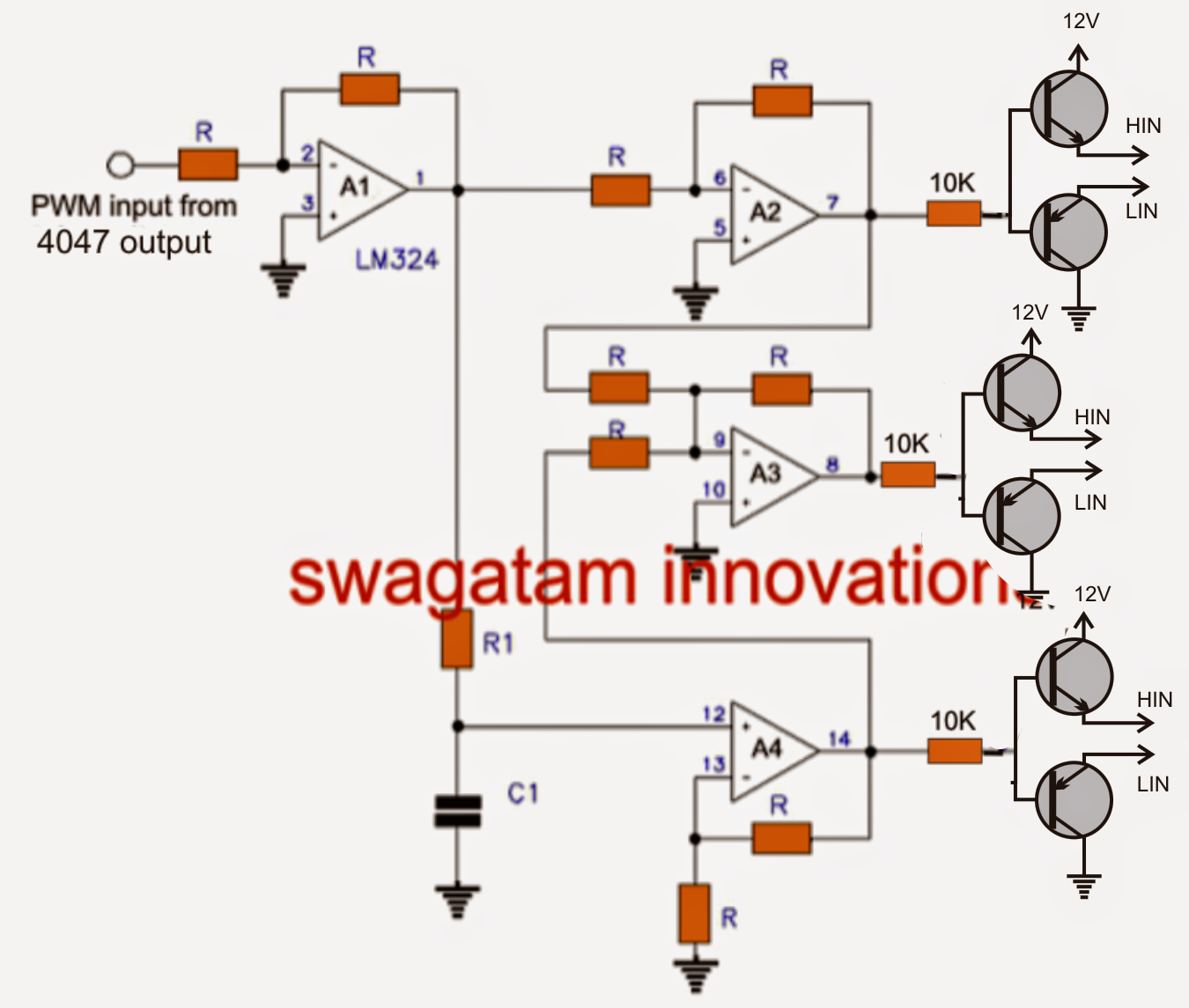
Download scientific diagram | 1): We have already studied an effective yet simple. The internet is flooded with single phase inverter circuit diagrams, but there are only few circuit diagrams of 3 phase inverter out there, a simplest possible 3 phase inverter is described here. The mosfet or igbt is used for switching purpose.
The wave shapes of line to line voltages.
The h bridge how to wire a 3 phase (inverter) washing machine motor to a variable frequency drive (vfd) automatic changeover switch The table for firing sequence can be used to define the steps of the three phase inverter for its 120° mode operation. “figure 2 circuit diagram of three phase inverter. Igbt is a mosfet and gtr composite device, so it has work fast, big input impedance, simple driving circuit, simple control circuit, higher operating frequency, large element capacity.
As this 3 phase inverter circuit diagram motor controller, it ends stirring inborn one of the favored.
Basically the switch is igbt or mosfet. It's hence unconditionally simple and for that reason fats, isn't it? The ucc21520 has many features to design a reliable three phase inverter. For 3 phases it has 3 legs.
Funda spwm 3 phase inverter step by step simulation on simulink pv inverter:
I have put together a bridge using 6 p55nf06 mosfets. As shown in circuit diagram, input dc voltage is. Three phase inverter design/circuit diagram. A basic three phase inverter is a six step bridge inverter.
This type of inverter requires two power electronics switches (mosfet).
It uses a minimum of 6 thyristors.


