First, consider a single circuit, as seen in the figure. The simple 1 watt led driver circuit buck converter presents approximately 90% efficiency. Before we get start building a 1 watt led dimmer circuit, first consider a simple circuit as shown in figure below.
Arduino Man over board light — Sailing in the
Q3’s collector then pulls q2’s base towards ground, switching it off, which in turn switches off the main pass transistor (q1).
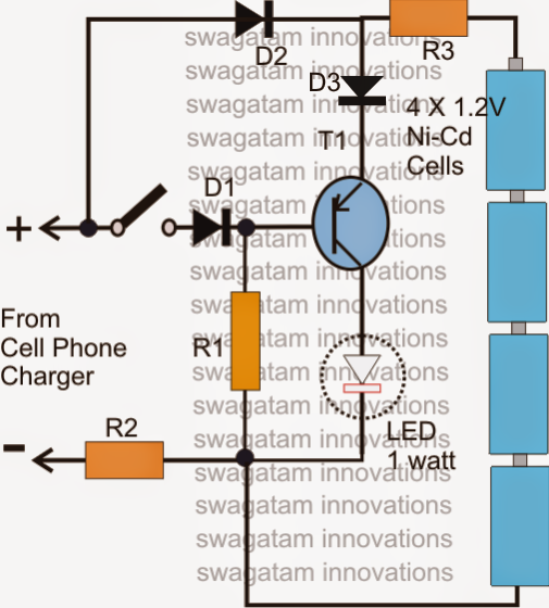
The led in the above diagram is a 12v 1 watt as shown below:
The concept discussed here remains exactly identical to the usual joule thief configuration, we just replace the normally used 5mm led with a 1 watt led. We know about the power source requirement to light an led. In this circuit, we will try to connect three 5mm white leds in parallel and light them up using a 12v supply. However, if you prefer to run the entire circuit continuously, use a 1 watt led alongside a led heat sink.
The circuit diagram of the high power led driver is shown in the image below.
In case you don’t have a 3.3 v standard power source, you can take higher voltages and add series resistor. Simple 7w led bulb circuit diagram designed to work by using 230v ac supply. Therefore, the value of rv1 value has a maximum current close to the 100ma pulse rating. As shown in the 1 watt led circuit diagram, if you have a 3.3 v standard voltage source you can direly connect it to led for making it work.
Led dimmer has mainly been designed to generate variable voltage over a fixed voltage, using a pwm (pulse width modulation) circuit based on the 555 timer ic.
Of course this would mean the battery. But, high power leds produce much amount of heat. The method of pwm is explained below. How an led driver circuit works and what are its uses.
The above circuit is designed to drive a led with 0.2a.
Due to increased temperature, leds lifetime reduces when operating above its temperature range. The above diagram shows a 3v led circuit, in this circuit there are two aa cells are used. The circuit diagram for leds in parallel connection is shown in the following image. 1 watt led dimmer circuit.
The present article discusses 3 such circuits, however here we replace the traditional 5mm led with a 1 watt led.
1w led circuit diagram circuit diagram shows a typical simple low cost solution with a zxsc310 driving a 1w led with a typical forward voltage of 3.4v at 300ma from a dual cell battery. The concept it to try to determine a running current by using the inductor, diode and load, at the same time the switch fills up the missing load energy on a single cycle. 1w, 4w, 6w, 10w, 12w led driver circuit smps. This article explains a simple 1w led driver circuit.
Transformer less circuit design makes this bulb very small and light weight.
Below is the form of pwm. This 7 watt led bulb circuit can be used as night lamp, garden lamp or night time gate lamp. You can indeed understand the complete circuit diagram through these pointers. In the above shown simple 1 watt led driver circuit, the two 4.7uf/250 capacitors along with the 10 ohm resistors form a kind of speed breaker in the circuit, this approach helps to arrest the initial switch on surge inrush which in turn helps to safeguard the led from getting.
20 watt led driver circuit diagram.
Circuit 3 of simple led circuits (leds in parallel) the final circuit in the simple led circuits tutorial is leds in parallel. Right here we research a very easy 120v/220v smps led driver circuit that can be used for driving high watt leds rated any place between 1 watt to 12 watts instantly from any domestic ac mains outlet. Transistors q1 and q2 are wired as an oscillator which produces positive pulses of width 20ms @ ½ hz. And the only way to change the.
Transistor q3 and mosfet q4 inverts this pulse and mosfet q5 drives the led d1.
1w 4w 6w 10w 12w led driver circuit smps. Here, current through led =. 1w led driver circuit diagram. This 1w led dimmer is primarily a 555 ic based pwm (pulse width modulation) circuit developed to get variable voltage over constant voltage.
Cob dob 50 watt led lightdosto is video me maine aapko cob dob light ko dikhaya h jo direct ac light se chalti h or isme driver ki jarurat nhi in this video we learn how to run 20 watt led bulb on 220v.
In this diy, we are demonstrating the project of a 1 watt led dimmer circuit. As you can see the driver has nothing more than a lm317 ic and a resistor. When you are operating an led with 3v you have to use minimum 10 ohms resistor. This is the circuit diagram a powerful led flasher.
3 volt basic led circuit with 10 ohms resistor.
This current rating is fixed by the resistor r1 in the circuit. The offered smps led driver circuit is exceedingly adaptable and in particular fitted to driving. Gate pulses n1 and n2 are operated as simple oscillators. A dual cell supply will have a voltage range of 1.8v to 2.5v for nicd and nimh type batteries and up to 3v for alkaline type batteries.
I = vref/r1 where, vref is 1.25v for lm317.
High power leds are very common in the market now and a 1w high power led is used here. Hence it can be fitted into small case.