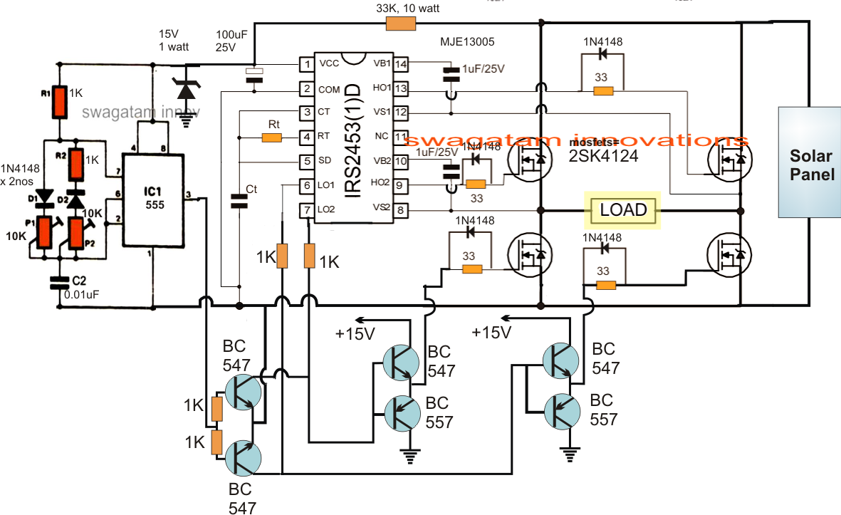
The project is based on the low cost egs002 spwm driver board module. Cutting edge software innovations allow for. 14/08/2015 · solar inverter circuit diagram:
Get solar Micro Inverter Wiring Diagram Download
Homemade 2000w power inverter with circuit diagrams.
Please slide to verify help help
When choosing an inverter for a. The entire design is configured around a single ic 4047 and a few power transistors. February 15, 2018 at 1:06 pm. The diy inverter board can handle up to 1kw (depending the transfor…
Diy cheap 1000w pure sine wave inverter (12v to 110v/220v):
A grid tied inverter is a special type of power inverter that converts pv output direct current electricity into alternating current electricity so that one can flow the electricity out into the. Shenzhen micno electric co ltd wifi monitoring hybrid anern bha 50a grid tie schematic mobile display off v2 open green 1kw mppt installing our renovated airstream part 2. To understand well how to construct a solar inverter, it is vital to study how the circuit operates through. (android & ios) it is compatible with 80v 30a solar panel setups and all battery chemistries up to 50v.
Few days ago, gohz made a 24v 2000w power inverter in home, sharing some design schematics and circuit diagrams.
The positive terminal of the inverter connects to the battery’s positive terminal, while the negative terminal of the inverter goes to the battery’s negative terminal. Total project cost is roughly around $25 ( sourced from the. The backup time provided by the inverter depends on the battery type and its current capacity. The purpose of this project is to design and construct a 1000watts (1kw) 220 volts inverter at a frequency of 50hz.
The basic block and circuit diagram of this project is as shown in figure 3.2 and 3.3 below.
Larger transformers and more powerful transistors can be substituted for t1, q1 and q2 for more power. 3.1.2 the inverter circuit this circuit charges and discharges the battery when there is ac mains supply and when the ac mains is not available respectively. Wiring diagram line we are make source the schematics, wiring diagrams and technical photos. The post explains a simple 48v inverter circuit which may be rated at as high as 2 kva.
Sorry, we have detected unusual traffic from your network.
Build a 1kw wifi mppt solar charge controller, equipped with phone app datalogging telemetry! Solar panel wiring diagram with inverter wiring diagram line wiring diagram. The inverter application requires two outputs that are 180 degrees out of phase. In this case, the solar inverter is connected to the batteries.
The project is based on an arduino esp32 and runs on my open source fugu mppt firmware!
Circuit design and construction of 1kw (1000va) power invertercell phone charger circuit. This device is constructed with locally sourced components and materials of regulated standards. It comprises a cd4047 multivibrator (ic1), irf250 mosfets (t1 through t8), transistors and a few discrete components. Next, plug the inverter into the grid, which acts as the input.
Car batteries for powering you home?
The basic principle of its operation is a simple conversion of 12v dc from a battery using integrated circuits and semiconductors at a frequency of 50hz, to. Real time monitors inverters remotely by data logger. Microcare inverters come with the latest software to improve the automatic change over from the grid to the inverter. Generally, inverter is a combination of a battery, a charger circuit and an inverting circuit as shown in the figure 3.1 below.


