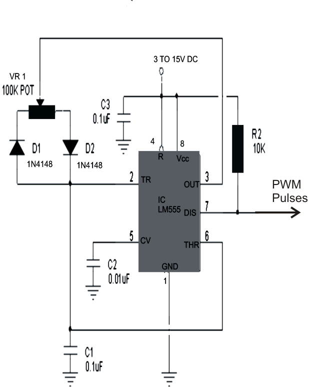
Bz 8668 schematics diagrams sine inverter 1000w schematic diagram. This power inverter has a good starting ability, it only takes about 1 second for two parallel 1000 watt solar lamps. The oscillating frequency is decided by external preset vr1 and capacitor c1.
1000W Inverter Circuit Diagram / China Kayal 1000w Dcac
1000w power inverter circuit diagram:
Simple 1000 watt pure sine wave inverter circuit is explained here using a signal amplifier and a power transformer.
A relatively simple 1000 watt pure sine wave inverter circuit is explained here using a signal amplifier and a power transformer. When autocomplete results are available use up and down arrows to review and enter to select. Last updated on august 3, 2020 by swagatam 217 comments. Td 6992 1000 watt power inverter schematic diagram for reference.
I have got pure sine wave in my final year project ” hybrid pure sine wave inverter ” after connecting a lc filter at the output of h bridge.i have lc values l= 2mh and c= 3.3uf.diagram of pure sine i have got in my final year project is shown in figure below:
This is the power inverter circuit based mosfet rfp50n06. 2000 watt pure sine wave inverter circuit diagram. Touch device users can explore by touch or with swipe gestures. 3 high power sg3525 pure sinewave inverter circuits.
Sine wave inverter circuit diagram with full explanation.
The inverter application requires two outputs that are 180 degrees out of phase. 1000w inverter pure sine wave schematic diagram datasheet. Last updated on august 3, 2020 by swagatam 241 comments. 1000w dc ac pure sine wave power inverter circuit diagram
As can be seen in the first diagram below, the configuration is a simple mosfet based designed for amplifying.
As can be seen in the first The inverter capable to handle loads up to 1000w, it’s depended on your power inverter transformer. A relatively simple 1000 watt pure sine wave inverter circuit is explained here using a signal amplifier and a power transformer. Car batteries for powering you home?
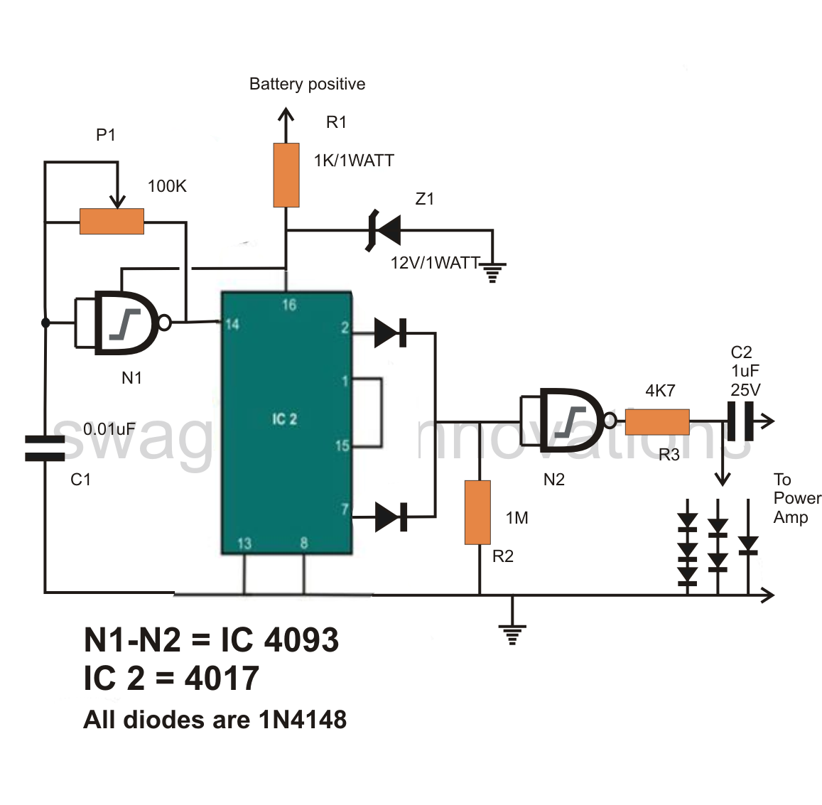
The first circuit is equipped with a low battery detection and cut off feature, and an automatic output voltage regulation feature.
Diy cheap 1000w pure sine wave inverter (12v to 110v/220v): The inverter capable to handle loads up to 1000w, it’s depended on your power inverter transformer. Make this 1kva (1000 watts) pure sine wave inverter circuit. Read pdf 1000w power inverter circuit diagram mylikeoremake this 1kva (1000 watts) pure sine wave inverter circuit.
The rfp50n06 fets are rated at 50 amps and 60 volts.
You may also interested in: Pictures made in 7 modified sine wave circuits explored 100w to 3kva make your own full explanation kayal manufacturer pure 1000w 24v solar s home 3000w lz2gl 1500 watt pwm sinewave egs002 resources easyeda 3000 120v ato customized 48v suppliers manufacturers factory whole ssth 1500w from. The diy inverter board can handle up to 1kw (depending the transfor… Pure sine wave inverter implementation and circuit diagram
Heatsink is required for cooling the mosfets.
The post explains a 3 powerful yet simple sine wave 12v inverter circuits using a single ic sg 3525. The rfp50n06 fets are rated at 50 amps and 60 volts. At no instant s1 and s2 should be on simultaneously, if such instants occur it. Touch device users, explore by touch or with swipe gestures.
100mh (0.1h) inductor, make sure you get high amperes rating ones.
Heatsink is required for cooling the mosfets. We have so many collections wire wiring diagrams and schematics, possibly including what is you need, such as a discussion of the inverter circuit diagram. Make this 1kva 1000 watts pure sine wave inverter circuit. **broken link removed** many thanks
1000w power inverter circuit diagram:
This inverter is designed to power about 2200 watt, the headline of this paper is 2000 watt is because the dc power supply maximum output current is 100a, so gohz tested it at 2000 watt, for more than 12 hours testing, it can work well at 2000 watt, there. You may add some mosfets with parallel… read more » 1cab005 inverter circuit diagrams 1000w wiring library.