Diy cheap 1000w pure sine wave inverter (12v to 110v/220v): It comprises a cd4047 multivibrator (ic1), irf250 mosfets (t1 through t8), transistors and a few discrete components. 4 power tubes of voltage boost portion.
1KVA (1000 watts) Pure Sine Wave Inverter Circuit
Car batteries for powering you home?
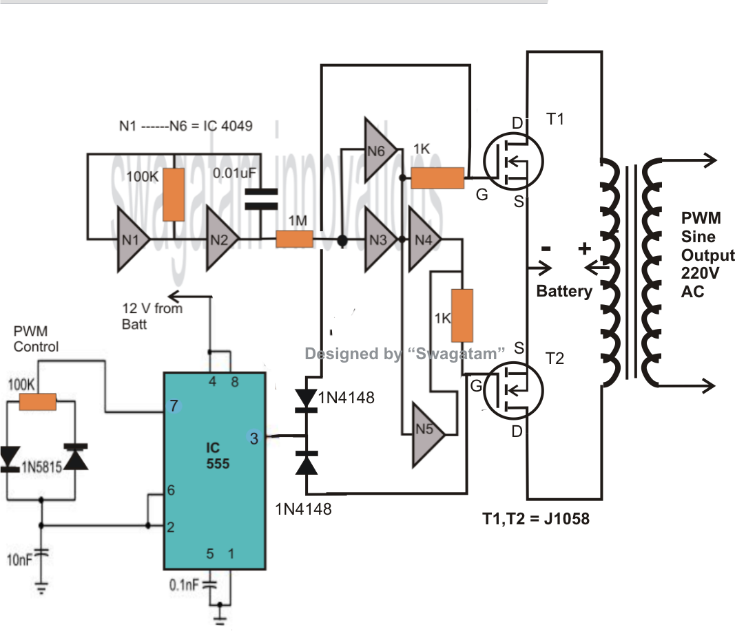
Simple 1000 watt pure sine wave inverter circuit is explained here using a signal amplifier and a power transformer.
The mosfets and the transformer of the above explained 1500 watt spwm inverter circuit are the two elements which determine the total power output. Last updated on august 3, 2020 by swagatam 219 comments. Red is the dc input positive pole 2. Egs002 driver board dimension diagram egs002 eg8010 + r2110s spwm driver board 6.0±0.2 32±0.3 61±0.3 1.9±0.1 a relatively simple 1000 watt pure sine wave inverter circuit is explained here using a signal amplifier and a power transformer.
This power inverter has a good starting ability, it only takes about 1 second for two parallel 1000 watt solar lamps.
The diy inverter board can handle up to 1kw (depending the transfor… As can be seen in the first diagram below, […] oyedele james. If equipped with a 15 amp front panel fuse, check fuse. Black is the dc input
1000 watt pure sine wave inverter circuit diagram in 2021 electronic circuit projects circuit diagram circuit.
A relatively simple 1000 watt pure sine wave inverter circuit is explained here using a signal amplifier and a power transformer. True sine wave inverter circuit circuit diagram sine wave pure products. When autocomplete results are available use up and down arrows to review and enter to select. Looking for simple sinewave inverter circuits which can be customized as per your specif electronic schematics electronic circuit projects electronics circuit.
This inverter is designed to power about 2200 watt, the headline of this paper is 2000 watt is because the dc power supply maximum output current is 100a, so gohz tested it at 2000 watt, for more than 12 hours testing, it can work well at 2000 watt, there.
The mosfets can be irfs4620trlpbf each. If unit is equipped with a circuit breaker, push button to reset. Black is the dc input negative pole 3. Pure sine wave inverter circuit using arduino make this 1kva (1000 watts) pure sine wave inverter circuit.
Touch device users can explore by touch or with swipe gestures.
As can be seen in the first diagram below, […] swagatam innovations. Now connect the battery bank’s output to a 40 watt 230v tungsten bulb, it. The home inverter overall structure is, downside is a large cooling plate, upside is a power board with same size as the cooling plate, length 228mm, width 140mm. Touch device users, explore by touch or with swipe gestures.
As can be seen in the first diagram below, the configuration is a simple mosfet based
Pure sine wave inverters draw power, either from standard 12 volt automobile and marine batteries, or from portable high power 12 volt sources. Pure sine wave inverter implementation and circuit diagram Replace 15 amp fuse and check for 110 vac at the inverter output wires. Connect the 27 (9v) batteries in series in the below shown schematic, it will give around 245vdc:
Read book pure sine wave inverter circuit using pic of inverter here.
Red is the dc input positive pole 2. This power inverter is designed for 12v dc, but also can be connected to 24v dc, my goal is 800 watt, strive to 1000 watt pure sine wave output. A relatively simple 1000 watt pure sine wave inverter circuit is explained I have got pure sine wave in my final year project ” hybrid pure sine wave inverter ” after connecting a lc filter at the output of h bridge.i have lc values l= 2mh and c= 3.3uf.diagram of pure sine i have got in my final year project is shown in figure below:
A relatively simple 1000 watt pure sine wave inverter circuit is explained here using a signal amplifier and a power transformer.
A relatively simple 1000 watt pure sine wave inverter circuit is explained here using a signal amplifier and a power transformer. Sine wave inverter circuit description. Is the 15 amp fuse good?