The on/off button on the inverter needs to be in position (in) for the inverter to invert battery As can be seen in the first diagram below, the configuration is a simple mosfet based designed for amplifying. This is a simple 12v 1000 watt inverter circuit diagram.
pure sine wave inverter circuit diagram 1000watts SHEMS
Read pdf 1000w power inverter circuit diagram mylikeoredepended on your power inverter transformer.
This inverter is designed to power about 2200 watt, the headline of this paper is 2000 watt is because the dc power supply maximum output current is 100a, so gohz tested it at 2000 watt, for more than 12 hours testing, it can work well at 2000 watt, there.
The inverter capable to handle loads up to 1000w, it’s depended on your power inverter transformer. Various “off the shelf” transformers can be used. The diy inverter board can handle up to 1kw (depending the transfor… The rfp50n06 fets are rated at 50 amps and 60 volts.
Mar 14, 2011 #1 m.
The rfp50n06 fets are rated at 50 amps and 60 volts. An illustrated guide | vanlife arduino pure sine wave inverter circuit with full program solar panel calculator and diy wiring diagrams for rv and building. The rfp50n06 fets are rated at 50 amps and 60 volts. Connect the 27 (9v) batteries in series in the below shown schematic, it will give around 245vdc:
You may add some mosfets with parallel… read more »
Make this 1kva (1000 watts) pure sine wave inverter circuit. The circuit built based ic cd4047 to generate sine wave signal 50hz and then the power transistor 2n3055 will boost the signal so that the signal have high power high electric current. This is the power inverter circuit based mosfet rfp50n06. 4 power tubes of voltage boost portion, 4 power tubes of h.
The inverter overall structure is, downside is a large cooling plate, upside is a power board with same size as the cooling plate, length 228mm, width 140mm.
Start date mar 14, 2011; Circuit diagram schematic of 1000 watt mosfet power inverter. Or custom wind your own for best results. The home inverter overall structure is, downside is a large cooling plate, upside is a power board with same size as the cooling plate, length 228mm, width.
The project is based on the low cost egs002 spwm driver board module.
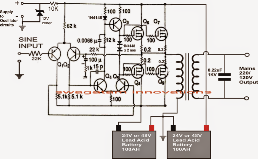
It is necessary to connect a fuse with the power line and always a load Inverter if circuit breaker is defective. This power inverter is designed for 12v dc, but also can be connected to 24v dc, my goal is 800 watt, strive to 1000 watt pure sine wave output. A relatively simple 1000 watt pure sine wave inverter circuit is explained here using a signal amplifier and a power transformer.
This power inverter is designed for 12v dc, but also can be connected to 24v dc, my goal is 800 watt, strive to 1000 watt pure sine wave output.
Low voltage battery cut off. Heatsink is required for cooling the mosfets. The xpower inverter 1000 is a quality inverter designed for recreational vehicle (rv) and truck applications. Frequency of operation is bent by a pot and is commonly set to 60 hz.
1000w power inverter circuit diagram:
This ability inverter ambit will accommodate a actual abiding “square wave” achievement voltage. • the inverter provides up to 1000 watts of continuous power. Heatsink is required for cooling the mosfets. 1000w 12v dc home power inverter circuit board design.
Status not open for further replies.
Car batteries for powering you home? Now connect the battery bank’s output to a 40 watt 230v tungsten bulb, it. Yes yes no no inverter will not provide 110 vac at output wire when operating on battery only. Unknown october 31, 2016 at 8:12 pm.
Diy cheap 1000w pure sine wave inverter (12v to 110v/220v):
This is the power inverter circuit based mosfet rfp50n06. 1000w power inverter circuit diagram: The inverter capable to handle loads up to 1000w, it’s depended on your power inverter transformer. Continuous output watts (watts) 1000.
Mazhara junior member level 1.
Sir, please tell me about the transformer core number for winding 1000 watt inverter transformer on this project. It is designed to handle loads such as 600 watt microwaves, tvs, vcrs, and midsized power tools. Heatsink is required for cooling the mosfets. 1000w power inverter circuit diagram mylikeore | f5f62de5a9ca1d075e462b4a364a5488 make this 1kva (1000 watts) pure sine wave inverter circuitcampervan solar power:
Last updated on august 3, 2020 by swagatam 241 comments.
Continuous output amps (amps) 8.5. Diagram, 1000w 12v dc home power inverter circuit board design, 1000 watt power inverter schematic electronics circuit, design and construction of 1kw 1000va power inverter, build a 250 to 5000 watts pwm dc ac 220v power inverter, 1000 watt power inverter schematic circuits projects, make this 1kva Joined dec 7, 2010 messages 16 helped 3 reputation 6 reaction score 3 trophy points 1,283 activity points 1,441